
Infrastructure Support for Accelerated Processing Device Memory Paging Without Operating System Integration

Active Publication Date: 2013-06-20
ATI TECH INC +1
View PDF6 Cites 47 Cited by
  • Summary
  • Abstract
  • Description
  • Claims
  • Application Information

AI Technical Summary

Benefits of technology

The present invention provides a CPU and GPU that share one physical space, with the combined architecture including infrastructure between the CPU and GPU. The improvement allows the GPU to manage its own memory without requiring changes to the operating system. This results in faster processing and better performance.

Problems solved by technology

These constraints arose from the fact that GPUs did not have as rich a programming ecosystem as CPUs.
Their use, therefore, has been mostly limited to two dimensional (2D) and three dimensional (3D) graphics and a few leading edge multimedia applications, which are already accustomed to dealing with graphics and video application programming interfaces (APIs).
Although OpenCL and DirectCompute are a promising start, there are many hurdles remaining to creating an environment and ecosystem that allows the combination of a CPU and a GPU to be used as fluidly as the CPU for most programming tasks.
Both of these arrangements, however, still include significant challenges associated with (i) separate memory systems, (ii) efficient scheduling, (iii) providing quality of service (QoS) guarantees between processes, (iv) programming model, and (v) compiling to multiple target instruction set architectures (ISAs)—all while minimizing power consumption.
While these external interfaces (e.g., chip to chip) negatively affect memory latency and power consumption for cooperating heterogeneous processors, the separate memory systems (i.e., separate address spaces) and driver managed shared memory create overhead that becomes unacceptable for fine grain offload.
This performance-based limitation exists because the CPU may relatively quickly require the results of the operations performed by these computational commands.
However, because of the high overhead of dispatching work to the GPU in current systems and the fact that these commands may have to wait in line for other previously-issued commands to be executed first, the latency incurred by sending computational commands to the GPU is often unacceptable.
Given that a traditional GPU may not efficiently execute some computational commands, the commands must then be executed within the CPU.
Having to execute the commands on the CPU increases the processing burden on the CPU and can hamper overall system performance.
Although GPUs provide excellent opportunities for computational offloading, traditional GPUs may not be suitable for system-software-driven process management that is desired for efficient operation in some multi-processor environments.
These limitations can create several problems.
For example, since processes cannot be efficiently identified and / or preempted, a rogue process can occupy the GPU hardware for arbitrary amounts of time.
In other cases, the ability to context switch off the hardware is severely constrained—occurring at very coarse granularity and only at a very limited set of points in a program's execution.
This constraint exists because saving the necessary architectural and microarchitectural states for restoring and resuming a process is not supported.
Lack of support for precise exceptions prevents a faulted job from being context switched out and restored at a later point, resulting in lower hardware usage as the faulted threads occupy hardware resources and sit idle during fault handling.

Method used


Image

  • Infrastructure Support for Accelerated Processing Device Memory Paging Without Operating System Integration
  • Infrastructure Support for Accelerated Processing Device Memory Paging Without Operating System Integration
  • Infrastructure Support for Accelerated Processing Device Memory Paging Without Operating System Integration

Examples


Embodiment Construction

[0013]What is needed is an improved combined CPU / GPU architecture. Additionally, an architecture which does not require any or significant changes to legacy operating systems would be desirable.

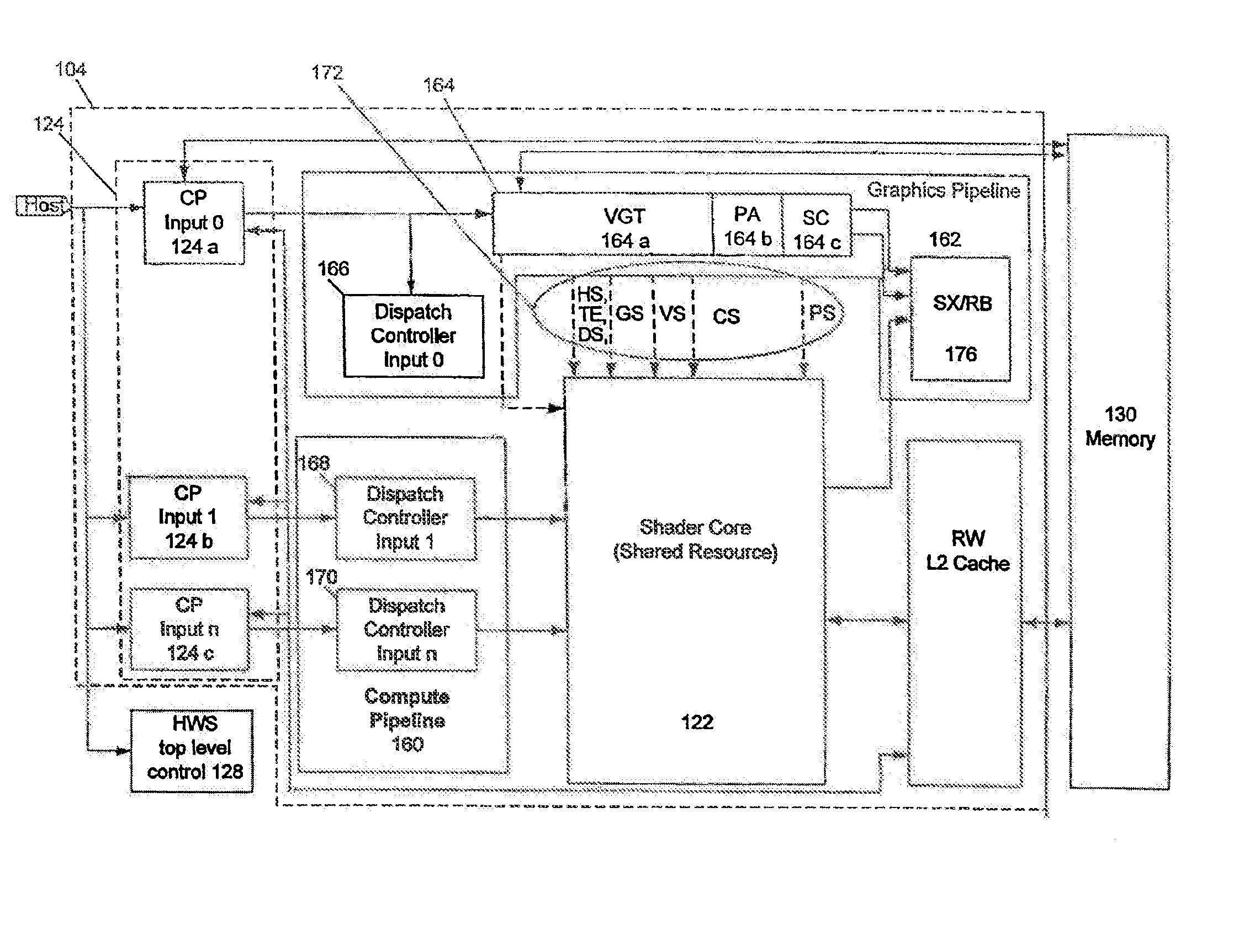
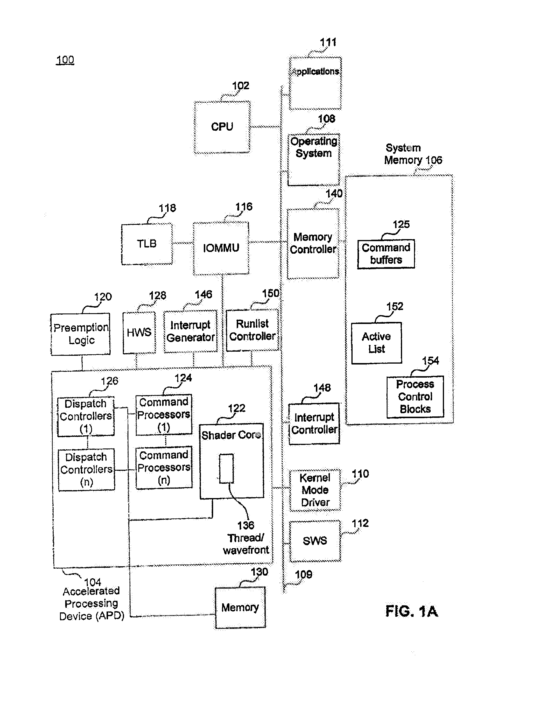
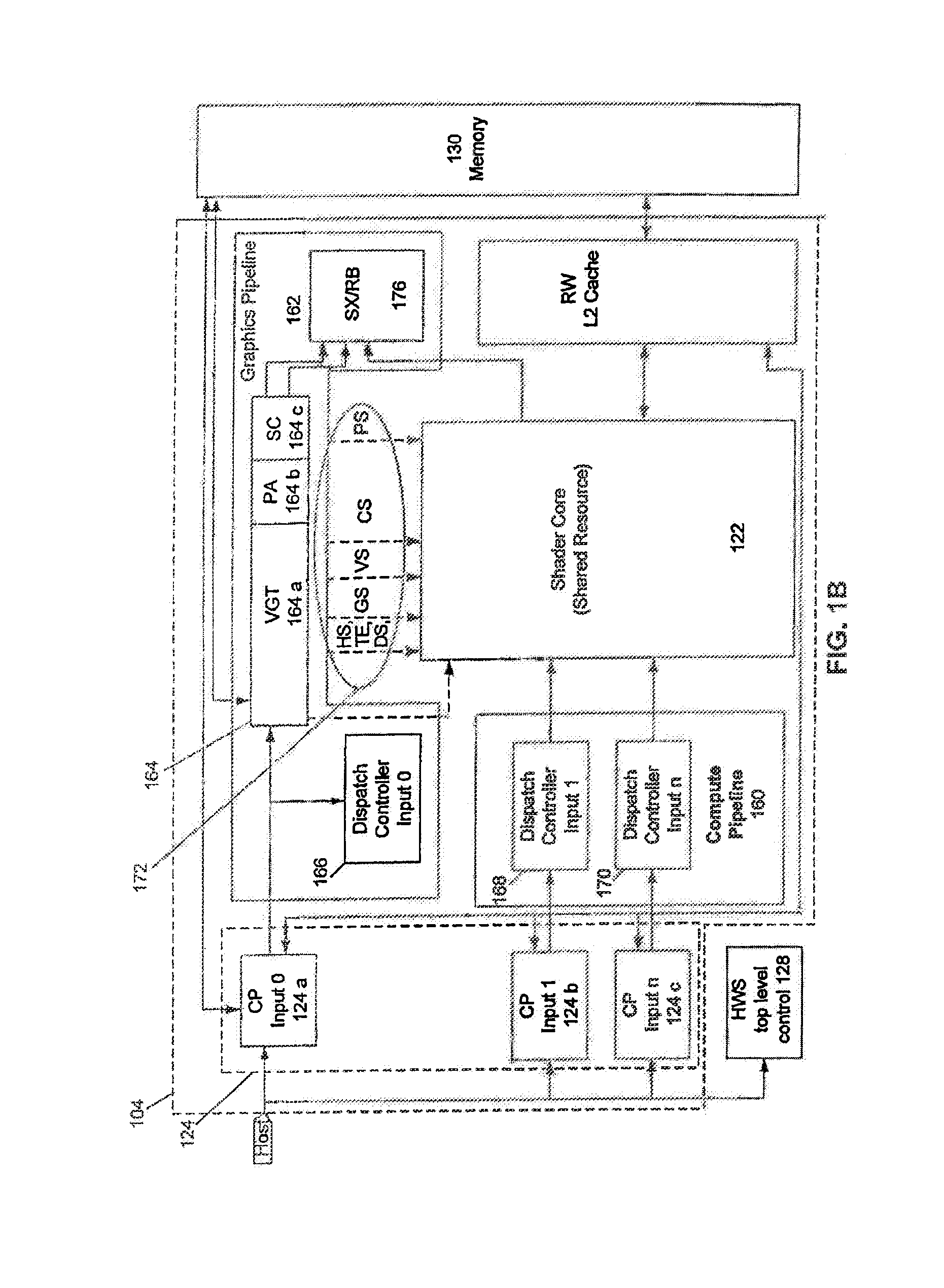
[0014]Certain embodiments of the present invention provide a CPU and GPU which share a unified address space and the combined CPU / GPU architecture includes infrastructure between the cores of the CPU and the I / O Memory Management Unit of the GPU. Also provided in certain embodiments of the present invention is an improved infrastructure that provides notification and control information flow to enable the use of the I / O Memory Management Unit of the GPU for the unified address space without requiring changes to legacy operating systems.

[0015]Although GPUs, accelerated processing units (APUs), and general purpose use of the graphics processing unit (GPGPU) are commonly used terms in this field, the expression “accelerated processing device (APD)” is considered to be a broader expression. For e...


PUM


Abstract

In a CPU of the combined CPU / APD architecture system, the CPU having multiple CPU cores, each core having a first machine specific register for receiving a physical page table / page directory base address, a second machine specific register for receiving a physical address pointing to a location controlled by an IOMMUv2 that is communicatively coupled to an APD, and microcode which when executed causes a write notification to be issued to the physical address contained in the second machine specific register; receiving in the first machine specific register of a CPU core, a physical page table / page directory base address, receiving in the second machine specific register of the CPU core, a physical address pointing to a location controlled by the IOMMUv2, determining that a control register of the CPU core has been updated, and responsive to the determination that the control register has been updated, executing microcode in the CPU core that causes a write notification to be issued to the physical address contained in the second machine specific register, wherein the physical address is able to receive writes that affect IOMMUv2 page table invalidations.

Description

BACKGROUND[0001]1. Field of the Invention[0002]The present invention is generally directed to computer systems. More particularly, the present invention is directed to processor architecture.[0003]2. Background Art[0004]The desire to use a graphics processing unit (GPU) for general computation has become much more pronounced recently due to the GPU's exemplary performance per unit power and / or cost. The computational capabilities for GPUs, generally, have grown at a rate exceeding that of the corresponding central processing unit (CPU) platforms. This growth, coupled with the explosion of the mobile computing market (e.g., notebooks, mobile smart phones, tablets, etc.) and its necessary supporting server / enterprise systems, has been used to provide a specified quality of desired user experience. Consequently, the combined use of CPUs and GPUs for executing workloads with data parallel content is becoming a volume technology.[0005]However, GPUs have traditionally operated in a constr...

Claims


Application Information

Patent Timeline
IPC IPC(8): G06F12/10
CPCG06F9/3004G06F12/1009G06F9/3881G06F2009/3883G06F12/1081G06F2212/683
Inventor BLINZER, PAULVAN DOORN, LEENDERT PETERCHENG, GONGXIAN JEFFREYTERRY, ELENEWOLLER, THOMAS ROYRAHMAN, ARSHAD
Owner ATI TECH INC
Learn More