Rechargeable partially implantable hearing instrument

a partially implantable, hearing instrument technology, applied in the direction of deaf-aid sets, electrical devices, deaf-aid sets, etc., can solve the problems of high operating cost, high operating cost, corrosion and malfunction, etc., and achieve the effect of keeping the complexity of the manufacturing process and the space requirements of the hearing instrument relatively low

Inactive Publication Date: 2013-07-18
ADVANCED BIONICS AG
View PDF7 Cites 8 Cited by
  • Summary
  • Abstract
  • Description
  • Claims
  • Application Information

AI Technical Summary

Benefits of technology

[0010]It is an object of the invention to provide for a partially implantable hearing instrument which can be recharged in a convenient manner, while keeping complexity of the manufacturing process and space requirements of the hearing instrument relatively low.
[0012]The invention is beneficial in that, by using the power transmission coil of the external unit of the hearing instrument for inducing a charging current to be used for recharging the rechargeable power source of the external unit by coupling it to an inductive charging device, convenient recharging of the power source of the external unit of the hearing instrument is enabled, namely in a wireless manner which eliminates the need for electrical contacts and which eliminates the need for removal of the batteries for recharging, while nevertheless the need for a separate charging coil of the external unit of the hearing instrument is avoided.

Problems solved by technology

Such batteries must be replaced frequently, with such replacement being cumbersome to the patient in view of the small size of such batteries.
In addition, the battery door is a potential source of moisture ingress into the hearing instrument housing, resulting in corrosion and malfunction.
In particular, in devices with high current consumptions, such as CIs and IMEHDs, battery lifetime is typically limited to one week or less, resulting in high operating costs.
This requires electrical contacts which are open to the environment and hence could become corroded.

Method used


Image

  • Rechargeable partially implantable hearing instrument
  • Rechargeable partially implantable hearing instrument
  • Rechargeable partially implantable hearing instrument

Examples


Embodiment Construction

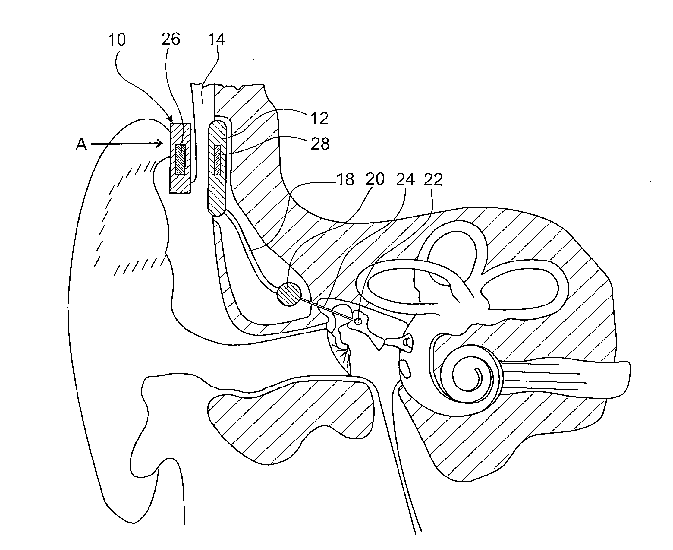
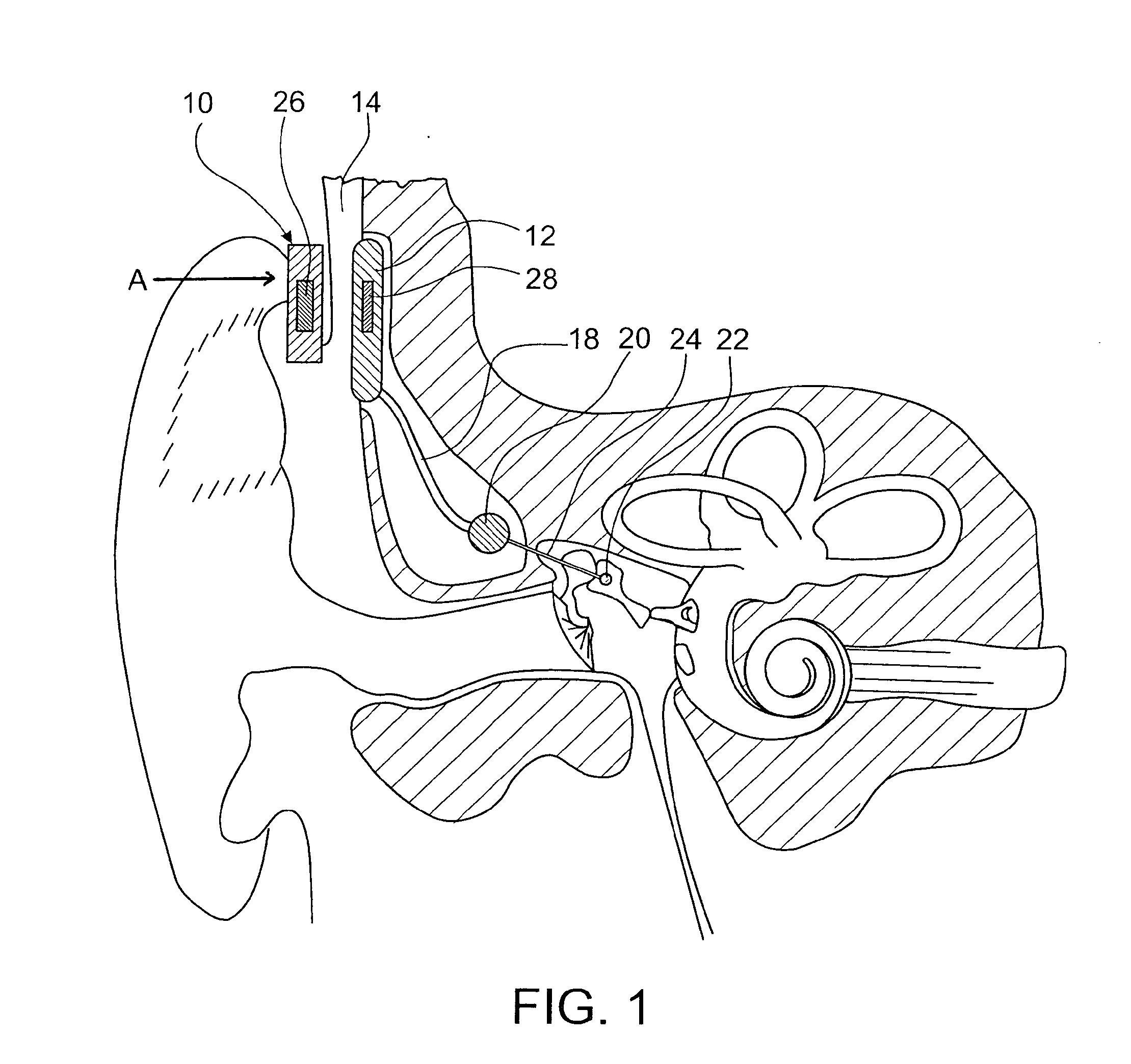
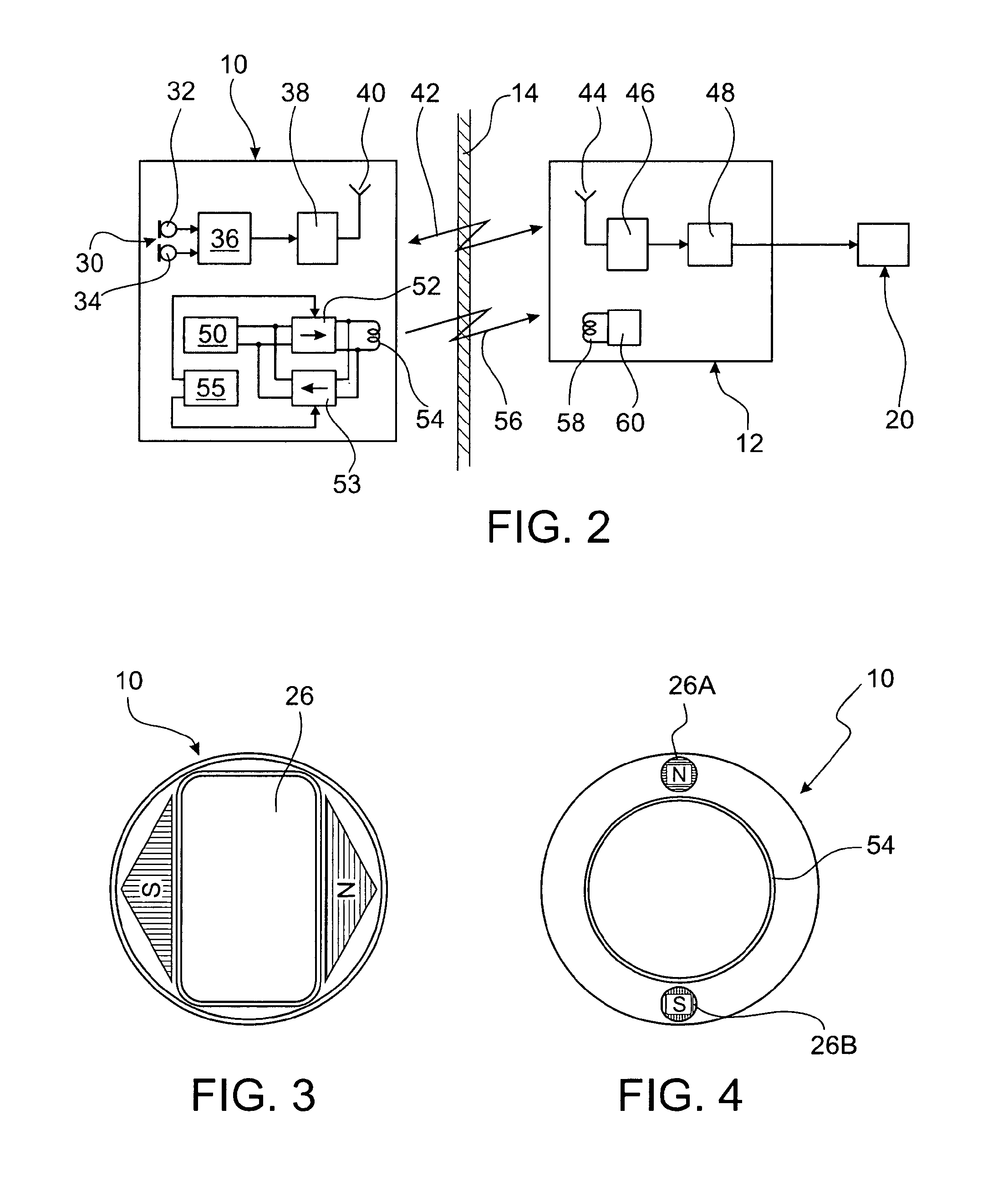
[0020]FIG. 1 shows a cross-sectional view of the mastoid region, the middle ear and the inner ear of a patient after implantation of an example of a hearing aid according to the invention, wherein the hearing aid is shown only schematically. The system comprises an external unit 10, which is worn outside the patient's body at the patient's head, and an implantable unit 12, which is implanted under the patient's skin 14, usually in an artificial cavity created in the user's mastoid. The implantable unit 12 is connected via a cable assembly 18 to an actuator 20. While in FIG. 1 an electromechanical actuator coupled to an ossicle 22 via a coupling rod 24 is shown, the actuator 20 also may be an electromechanical actuator coupled directly to the cochlear wall, an actuator directly acting on the perilymph or a cochlear electrode.

[0021]The external unit 10 is fixed at the patient's skin 14 in a position opposite to the implantable unit 12, for example, by magnetic forces created between a...


PUM


Abstract

A system has an implantable unit and an external unit. The external unit is fixable at the patient's head and has an audio signal source, an audio signal processing unit for processing audio signals from the audio signal source, a rechargeable power source, a transmitter for transmitting processed audio signals via a transcutaneous audio link to the implantable unit and a power transmission coil for transmitting power via a transcutaneous power link to the implantable unit. The implantable unit has a stimulator for a patient's middle ear or inner ear component according to the processed audio signals. The external unit is coupleable to the inductive charging device for inducing an AC voltage in the power transmission coil. The external unit has a recharging circuitry for transforming the AC voltage induced in the power transmission coil by the charging device into a charging current for recharging the rechargeable power source.

Description

BACKGROUND OF THE INVENTION[0001]1. Field of the Invention[0002]The present invention relates to a system comprising a partially implantable hearing instrument and a charging device for recharging the power source of an external unit of the hearing instrument, which external unit is to be fixed at the patient's head and supplies an implantable unit of the hearing instrument with power via a transcutaneous power link.[0003]2. Description of Related Art[0004]Typically, both electro-acoustic hearing aids and the external part of partially implantable hearing instruments, such as cochlea implants (CIs) and middle ear hearing devices (IMEHDs) are powered by zinc-air non-rechargeable batteries. Such batteries must be replaced frequently, with such replacement being cumbersome to the patient in view of the small size of such batteries. In addition, the battery door is a potential source of moisture ingress into the hearing instrument housing, resulting in corrosion and malfunction. In part...

Claims


Application Information

Patent Timeline
Patent Type & Authority Applications(United States)
IPC IPC(8): H04R25/00
CPCH04R25/55H04R25/602H04R25/606H04R25/554
Inventor BUEHLMANN, FELIX
Owner ADVANCED BIONICS AG
Why Eureka
Try Eureka