Carbon nanotube conductor with enhanced electrical conductivity

a carbon nanotube and electrical conductivity technology, applied in the field of conductors, can solve the problems of significant reduction of the conductivity properties of high alternating current signal frequency, large specific surface area of cnts, and difficulty in utilizing conventional metals such as copper and silver for electrical power conductors and signal transmission cables for airborne and space system applications

Active Publication Date: 2013-07-18
NORTHROP GRUMMAN SYST CORP
View PDF8 Cites 14 Cited by
  • Summary
  • Abstract
  • Description
  • Claims
  • Application Information

AI Technical Summary

Problems solved by technology

CNTs have extremely small size and extremely large specific surface area.
Utilization of conventional metals such as copper and silver for electrical power conductors and signal transmission cables for airborne and space system applications is problematic.
Moreover, due to their macro- or bulk nature (non-nanometer dimension scale), these metal conductors are subject to a “skin effect” which significantly reduces their conductivity properties at high alternating current signal frequencies.
While aluminum conductors have similarly high electrical conductivity and are substantially less dense than copper or silver, aluminum wire mechanical properties are markedly inferior and are not generally considered reliable enough for air and space systems.
Aluminum conductors—due to their lower strength, fatigue life and service temperature—have not been used for applications requiring ultra-high reliability such as spacecraft for which repair or replacement is not a practical option.
However, the electrical conductivity of these CNT materials is not optimum for many of the intended applications.
Attempts to achieve a targeted conductance value through adding and / or removing material, electrochemical plating, conductor compression and / or tensioning, and other mechanical means can be difficult to accomplish and can negatively impact conductor strength, flexibility and fatigue or cycle life.
Unfortunately, these methods do not provide the flexibility for achieving a targeted conductivity and / or may alter the mechanical properties of the conductor.

Method used


Image

  • Carbon nanotube conductor with enhanced electrical conductivity
  • Carbon nanotube conductor with enhanced electrical conductivity
  • Carbon nanotube conductor with enhanced electrical conductivity

Examples


Embodiment Construction

[0016]While the present invention is susceptible of embodiment in many different forms, there is shown in the drawings and will herein be described in detail one or more specific embodiments, with the understanding that the present disclosure is to be considered as exemplary of the principles of the invention and not intended to limit the invention to the specific embodiments shown and described. In the following description and in the several figures of the drawings, like reference numerals are used to describe the same, similar or corresponding parts in the several views of the drawings.

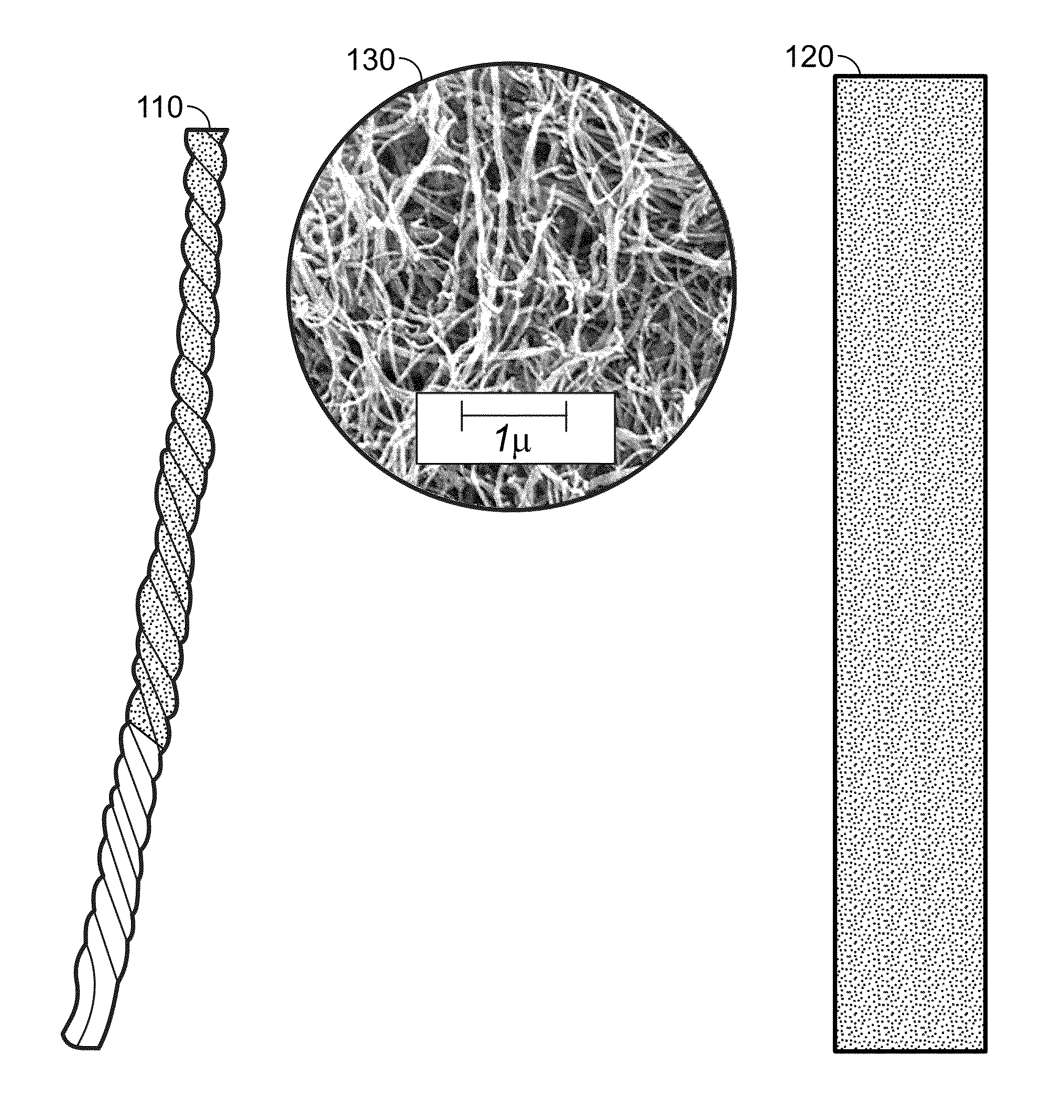
[0017]Utilization of conventional metals such as copper and silver for electrical power conductors and signal transmission cables for airborne and space system applications is problematic. These applications, depending on their scale, can require hundreds to several thousand kilometers of wire and cabling and need to be lightweight in order to minimize their impact on overall system performance. Wh...


PUM

PropertyMeasurementUnit
densityaaaaaaaaaa
densitiesaaaaaaaaaa
densitiesaaaaaaaaaa

Abstract

A method includes the steps of receiving a conductor element formed from a plurality of carbon nanotubes; and exposing the conductor element to a controlled amount of a dopant so as to increase the conductance of the conductor element to a desired value, wherein the dopant is one of bromine, iodine, chloroauric acid, hydrochloric acid, hydroiodic acid, nitric acid, and potassium tetrabromoaurate. A method includes the steps of receiving a conductor element formed from a plurality of carbon nanotubes; and exposing the conductor element to a controlled amount of a dopant solution comprising one of chloroauric acid, hydrochloric acid, nitric acid, and potassium tetrabromoaurate, so as to increase the conductance of the conductor element to a desired value.

Description

BACKGROUND[0001]The invention relates generally to a conductor and more particularly to a carbon nanotube (CNT) conductor with enhanced electrical conductivity.[0002]CNTs are 1-dimensional, nanometer-scale, tubular-shaped graphene molecules that exhibit ballistic semiconducting and metallic electrical conductivity properties at room temperature. CNTs have extremely small size and extremely large specific surface area. CNTs are known to have extraordinary tensile strength, including high strain to failure and relatively high tensile modulus. CNTs may also be highly resistant to fatigue, radiation damage, and heat.[0003]CNTs comprise sp2 covalently bonded carbon atoms in a hexagonal array and have a relatively low density of around 1,400 kg / m3. Due to void volume, spun CNT yarns, braided cable and manufactured sheet products can have densities as much as ⅔ lower than this figure. CNTs may be produced as single- or multi-wall tubular structures by a variety of synthesis methods and can...

Claims


Application Information

Patent Timeline
Patent Type & Authority Applications(United States)
IPC IPC(8): B05D5/12B82Y30/00B82Y40/00
CPCH01B1/04B05D5/12B05D7/20H01B13/0036C23C14/00C23C14/48B05D2256/00C01B32/05
Inventor STARKOVICH, JOHN A.SILVERMAN, EDWARD M.PENG, HSIAO-HU
Owner NORTHROP GRUMMAN SYST CORP
Why Eureka
Try Eureka