Laser ignition system

a laser beam and ignition system technology, applied in the direction of electric ignition installation, mechanical equipment, machines/engines, etc., can solve the problems of reducing the number of molecules which can absorb laser beams, degrading ignition performance, and reducing the absorption of laser beams, so as to enhance the ignition performance of internal combustion engines and reduce size , the effect of simple configuration

Inactive Publication Date: 2013-07-25
NIPPON SOKEN +1
View PDF3 Cites 21 Cited by
  • Summary
  • Abstract
  • Description
  • Claims
  • Application Information

AI Technical Summary

Problems solved by technology

However, even in such a laser ignition system, when the gaseous mixture concentration is lowered, the number of molecules which can absorb a laser beam decreases to degrade ignition performance.
When the gaseous mixture concentration in the vicinity of the ignition timing in the combustion chamber has deviation and a laser beam is oscillated in a region in which the gaseous mixture concentration is low, the absorption of the laser beam decreases and a flame spread rate also decreases, thereby not producing good combustion.
In an engine having a large bore diameter, even when ignition is successful, the spread of combustion takes much time and the flame may be extinguished without reaching complete explosion.
However, in the laser ignition system disclosed in publication of unexamined Japanese patent application No. 2006-161612, since one laser beam is split by combining plural total reflecting mirrors and half reflecting mirrors and the split laser beams are condensed in the combustion chamber, the split laser beams are condensed on plural condensing points in the combustion chamber simultaneously or almost simultaneously with a very short time difference due to the difference in optical path length, and the ignited combustion starts almost simultaneously from all the condensing points.
Accordingly, adjustment of ignition start timings at plural condensing points in the combustion chamber and ignition control corresponding to the gaseous mixture status of the engine are not able to be performed.
As shown in FIG. 2 of publication of unexamined Japanese patent application No. 2006-161612, in the configuration where a laser beam having high energy enters a vertex of a polygonally pyramidal beam splitting prism having plural refractive faces, passes through the beam splitting prism, and exits from plural refractive faces, when the entrance position of a laser beam very slightly departs from the vertex of the beam splitting prism, the laser beam is not uniformly split and plural laser beams exiting into the engine combustion chamber are uneven in energy, whereby stable ignition performance may not be secured.
In order to avoid such a problem with the configuration disclosed in publication of unexamined Japanese patent application No. 2006-161612, very high processing precision is required for causing a laser beam to accurately enter the vertex of the beam splitting prism, thereby causing an increase in manufacturing cost.
Accordingly, in order to obtain the energy necessary for ignition, it is necessary to increase the energy of a laser beam, thereby causing an increase in system size, an increase in cost, and a decrease in fuel efficiency.
Accordingly, a desired number of condensing points cannot be obtained or a decrease in energy may be caused due to fine-splitting of a laser beam.

Method used


Image

  • Laser ignition system
  • Laser ignition system
  • Laser ignition system

Examples


first embodiment

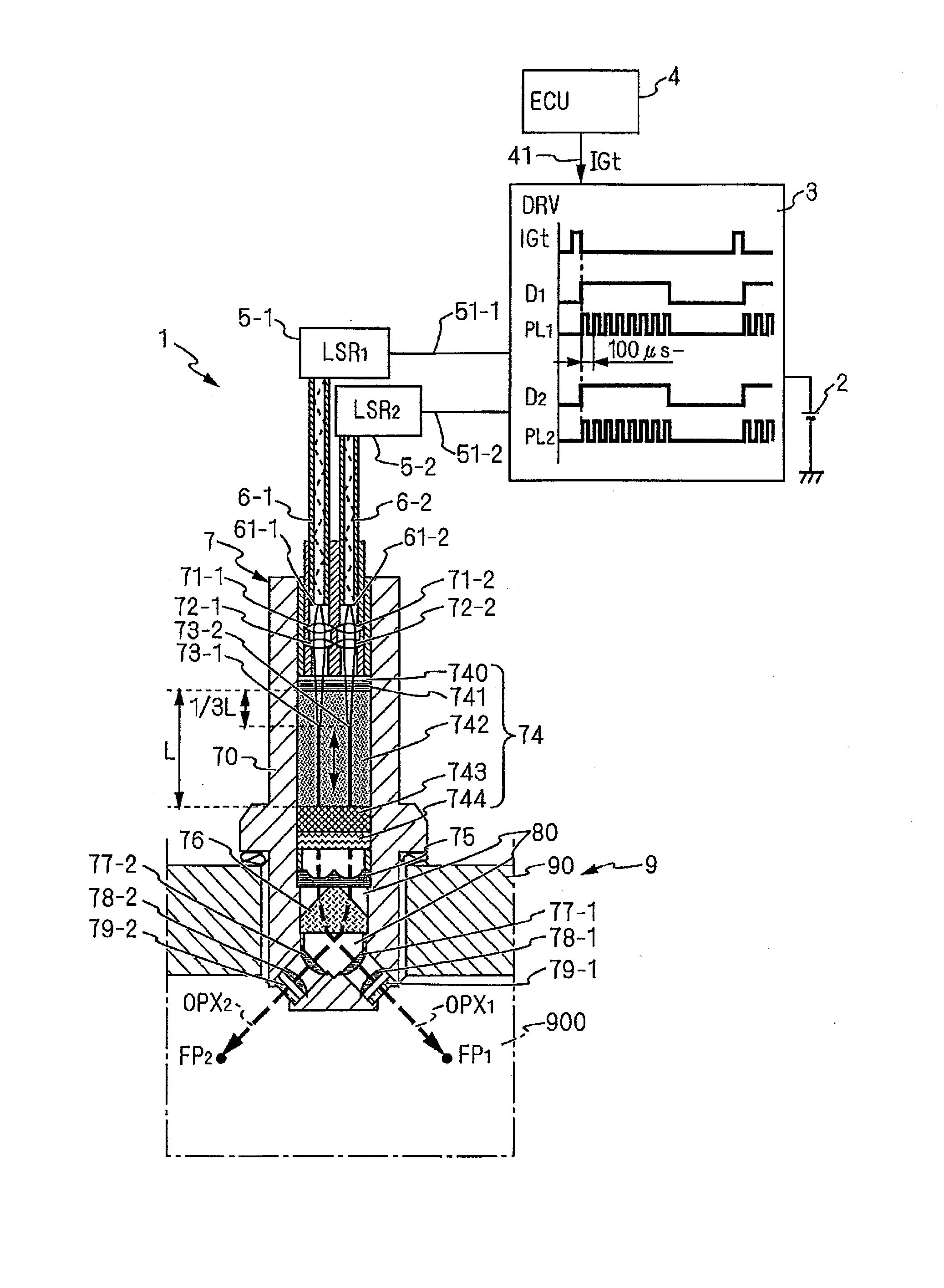
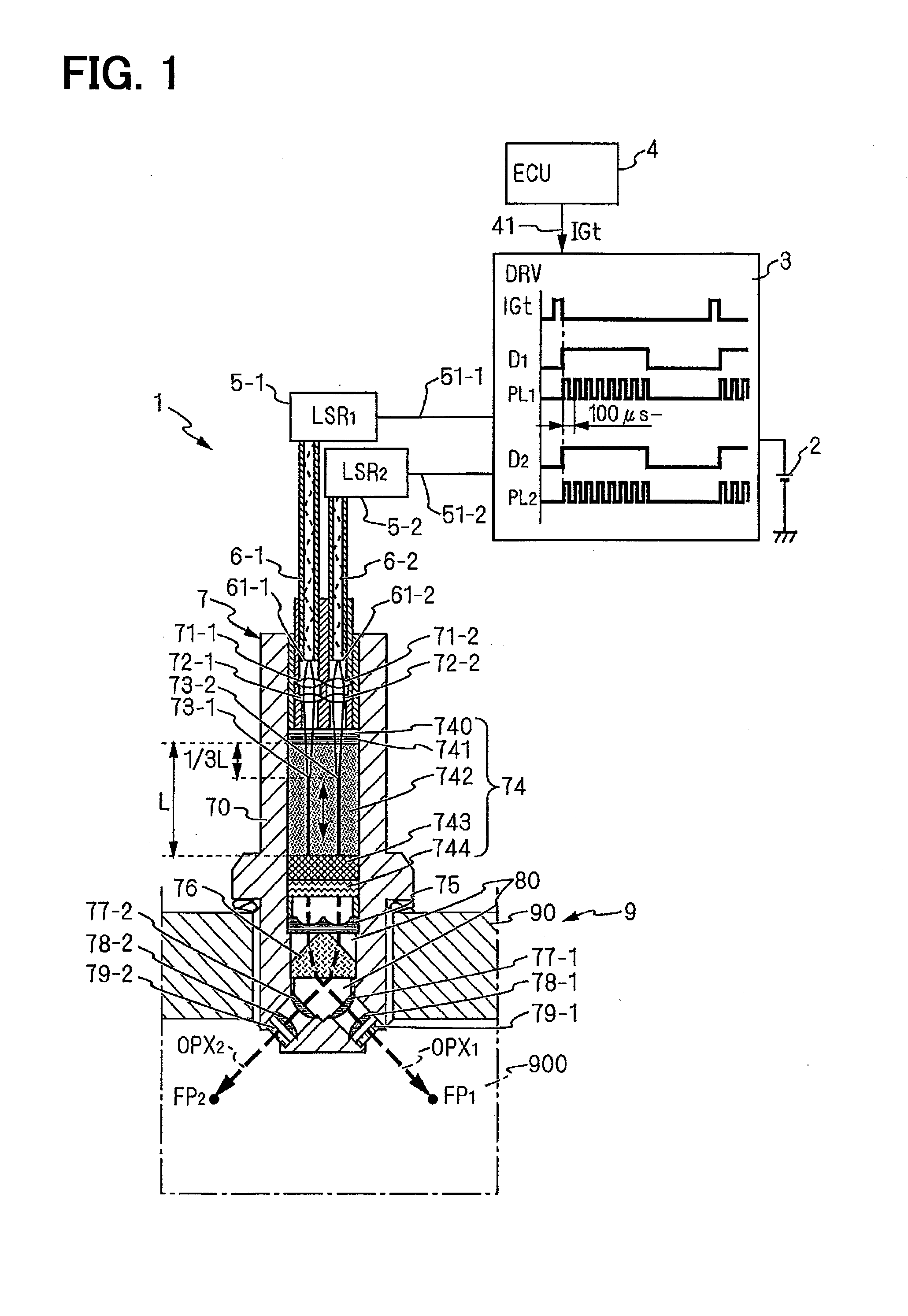
[0045]The configuration and operation of a laser ignition system 1 according to a first embodiment of the invention will be described with reference to FIGS. 1 and 2. The laser ignition system 1 according to the first embodiment is an ignition system that is mounted on a cylinder head 90 of an internal combustion engine 9 not drawn and that greatly refracting optical axes OPX1 and OPX2 of plural laser beams by using a highly-refractive optical element 76, condenses the laser beams on plural condensing points FP1 and FP2 in an engine combustion chamber 900, generates flame kernels at plural positions in the engine combustion chamber 900 to ignite a gaseous mixture. Particularly, use for ignition of an ignition-retardant highly-supercharged engine, a highly-compressed engine, a thin gaseous mixture engine, and the like is assumed.

[0046]The laser ignition system 1 includes a power source 2, a semiconductor laser driving circuit (DRV) 3, an engine ECU 4, plural semiconductor lasers 5-1 ...

second embodiment

[0071]A laser ignition system le according to a second embodiment of the invention will be schematically described with reference to FIG. 8. The configuration in which the laser beams exiting from the resonator 74 are expanded by the beam expander 75 and are refracted by the highly-refractive optical element 76 is described in the above-mentioned embodiment, but a configuration in which laser beams exiting from the resonator 74 are refracted by a highly-refractive optical element 76e, are then expanded once by beam expanders 75e-1 and 75e-2, and are additionally condensed by condenser lenses 77e-1, 77e-2, 78-1 and 78-2 may be employed as shown in FIG. 8. At this time, parts of the beam expanders 75e-1 and 75e-2 may be cut to form a petal-like shape and may be intensively unified, like the condenser lenses 77-1 and 77-2 shown in FIGS. 5A to 5C and FIGS. 6A to 6D.

[0072]The condenser lenses 77e-1 and 77e-2 in this embodiment are not unified unlike the above-mentioned embodiment, but a...

third embodiment

[0073]A laser ignition system according to a third embodiment of the invention will be schematically described with reference to FIGS. 9A and 9B. The configuration in which the beam expander 75 and the highly-refractive optical element 76 are separately formed is described in the above-mentioned embodiment, but this embodiment is different from the above-mentioned embodiment in that, as a highly-refractive optical element 76f, concave face portions 751f- 1751f-2 are formed on the exit face of the highly-refractive optical element 76f as shown in FIG. 9B, and a part of the highly-refractive optical element 76f also serves as the beam expander 75. The optical axes OPX1 and OPX2 of the laser beams entering the entrance faces 761f-1 and 761f-2 at an incidence angle θ1 are refracted by a refraction angle θ2 and the laser beams are expanded when exiting from the concave face portions 751f-1 and 751f- 2. The same advantages as in the above-mentioned embodiment are achieved in this embodim...


PUM


Abstract

A laser ignition system that is mounted on an internal combustion engine and that condenses a laser beam oscillated from a laser oscillator into an engine combustion chamber by using a condenser lens to generate a flame kernel with high energy and to perform ignition includes at least a highly-refractive optical element that refracts optical axes OPX1 to OPXn of plural laser beams oscillated from plural semiconductor lasers 5-1 to 5-n through a resonator to change traveling directions of the laser beams and a condenser device that condenses the laser beams refracted by the highly-refractive optical element on plural positions FP1 to FPn in the engine combustion chamber.

Description

CROSS-REFERENCE TO RELATED APPLICATIONS[0001]This application is based upon and claims the benefit of priority from Japanese Patent Application No. 2010-210411 filed on Sep. 21, 2010 and Japanese Patent Application No. 2011-12645 field on Jan. 25, 2011, the entire contents of which are incorporated herein by reference.TECHNICAL FIELD[0002]The present invention relates to a laser ignition system used for ignition of an internal combustion engine.BACKGROUND ART [0003]Recently, from the viewpoint of reducing CO2 emission, highly-supercharged and highly-compressed vehicle engines which are small-sized and which can achieve high output power and dynamo engines of a cogeneration system which can achieve high efficiency and low NOx have been developed. In the highly-supercharged and highly-compressed vehicle engines, the cylinder pressure before ignition is high. Accordingly, when ignition is performed using a sparking plug, it is necessary to increase energy to be supplied to the sparking...

Claims


Application Information

Patent Timeline
Patent Type & Authority Applications(United States)
IPC IPC(8): F02P23/04
CPCF02P15/08F02P23/04H01S3/0071H01S3/2383H01S3/094053H01S3/09415H01S3/113H01S3/0627F02P15/02
Inventor KANEHARA, KENJIPAVEL, NICOLAIETAIRA, TAKUNORITSUNEKANE, MASAKI
Owner NIPPON SOKEN
Why Eureka
Try Eureka