Sense circuit and method of operation thereof and photoelectric conversion array

a technology of sense circuit and photoelectric conversion array, which is applied in the direction of optical radiation measurement, radiation controlled devices, instruments, etc., can solve the problem of difficult arraying a large number of sense circuits

Inactive Publication Date: 2013-07-25
NAT INST OF ADVANCED IND SCI & TECH +1
View PDF8 Cites 9 Cited by
  • Summary
  • Abstract
  • Description
  • Claims
  • Application Information

AI Technical Summary

Benefits of technology

[0099]the photoelectric conversion cell is configured so that the third emitter in the photoelectric conversion cell is connected to one of a third drain and a third source of a third field effect transistor, a third gate of the third field effect transistor serves as the control section, the other of the third drain and the third source serves as the output section, and a specified potential is connected to either the first collector, the second collector or the third collector.

Problems solved by technology

Instead, an array of sense circuits provided for each output line is used for high sensing speed, but the sense circuits are required to suppress variations in amplification factor, and therefore, the circuit becomes complicated and occupies a large area on a semiconductor chip, which in turn renders it difficult to array a large number of sense circuits (for example, more than 1000 sense circuits).

Method used


Image

  • Sense circuit and method of operation thereof and photoelectric conversion array
  • Sense circuit and method of operation thereof and photoelectric conversion array
  • Sense circuit and method of operation thereof and photoelectric conversion array

Examples


Embodiment Construction

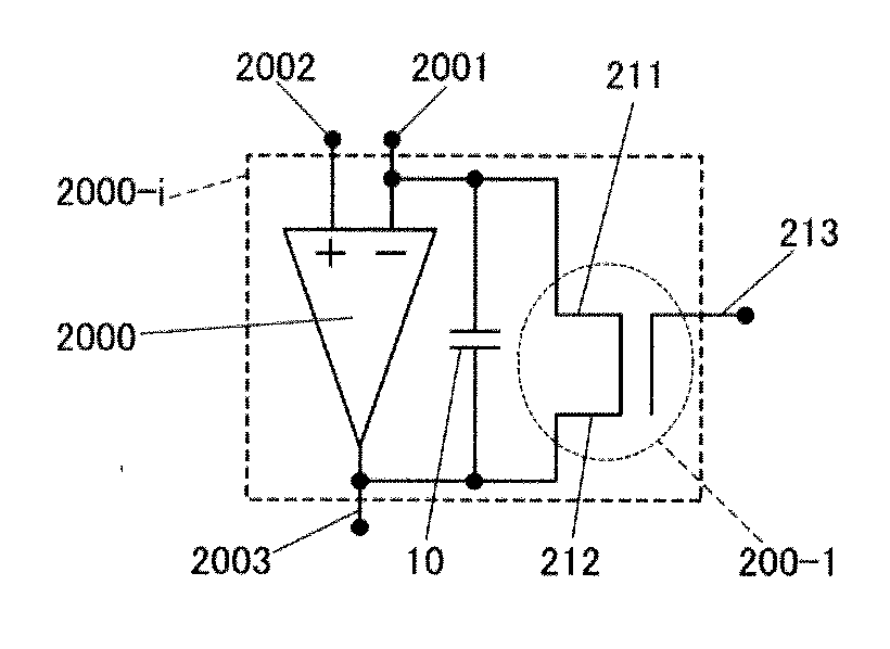
[0118]FIG. 1 is a circuit diagram illustrating a first embodiment of a sense circuit 2000-i of the present invention. A differential amplifier circuit 2000 includes an inverting input section 2001, a non-inverting input section 2002, and an output section 2003, and an electrical capacitor 10 is connected between the inverting input section 2001 and the output section 2003. Also, the inverting input section 2001 is connected to one 211 of a first source and a first drain of a first field effect transistor 200-1, and the output section 2003 is connected to the other 212 of the first source and the first drain of the first field effect transistor 200-1.

[0119]The non-inverting input section 2002 is supplied with a reference potential. The inverting input section 2001 has a connection to an output section of a photoelectric conversion cell to output an electric current or electric charge. The photoelectric conversion cell includes a control section besides the output section; when an out...


PUM


Abstract

A sense circuit includes a differential amplifier circuit including an inverting input section, a non-inverting input section and an output section, an electrical capacitor connected between the inverting input section and the output section, and a field effect transistor including a source, a drain, and a gate. One of the source and the drain is connected to the inverting input section, and the other of the source and the drain is connected to the output section. A reference potential is supplied to the non-inverting input section, and an output section of a photoelectric conversion cell having an added switching function is connected to the inverting input section.

Description

CROSS-REFERENCE TO RELATED APPLICATION[0001]This application is based on and claims the priority benefit of Japanese Patent Application No. 2012-008686, filed on Jan. 19, 2012, the disclosure of which is incorporated herein by reference in its entirety.BACKGROUND OF THE INVENTION[0002]1. Field of the Invention[0003]The present invention relates to a sense circuit for use in a photoelectric conversion device or an image sensing device or the like for converting optical information such as light intensity or light wavelength or an optical image into electric current, electric charge or voltage, or electronic information containing digital data, and a method of operation of the sense circuit, and a photoelectric conversion array using the sense circuit.[0004]2. Description of the Related Art[0005]In the case of a photoelectric conversion cell in which an electronic information output is a voltage output, such as a CMOS (complementary metal oxide semiconductor) sensor, a voltage amplifi...

Claims


Application Information

Patent Timeline
Patent Type & Authority Applications(United States)
IPC IPC(8): H01L27/144
CPCH04N5/378H01L27/144H04N25/75
Inventor HAYASHI, YUTAKAOTA, TOSHITAKANAGAMUNE, YASUSHIWATANABE, HIROFUMIYONEDA, KAZUHIROAISU, KATSUHIKONEGORO, TAKAAKI
Owner NAT INST OF ADVANCED IND SCI & TECH
Why Eureka
Try Eureka