Light-emitting element and method for manufacturing same

Active Publication Date: 2013-07-25
SEOUL NAT UNIV R&DB FOUND
View PDF2 Cites 44 Cited by
  • Summary
  • Abstract
  • Description
  • Claims
  • Application Information

AI Technical Summary

Benefits of technology

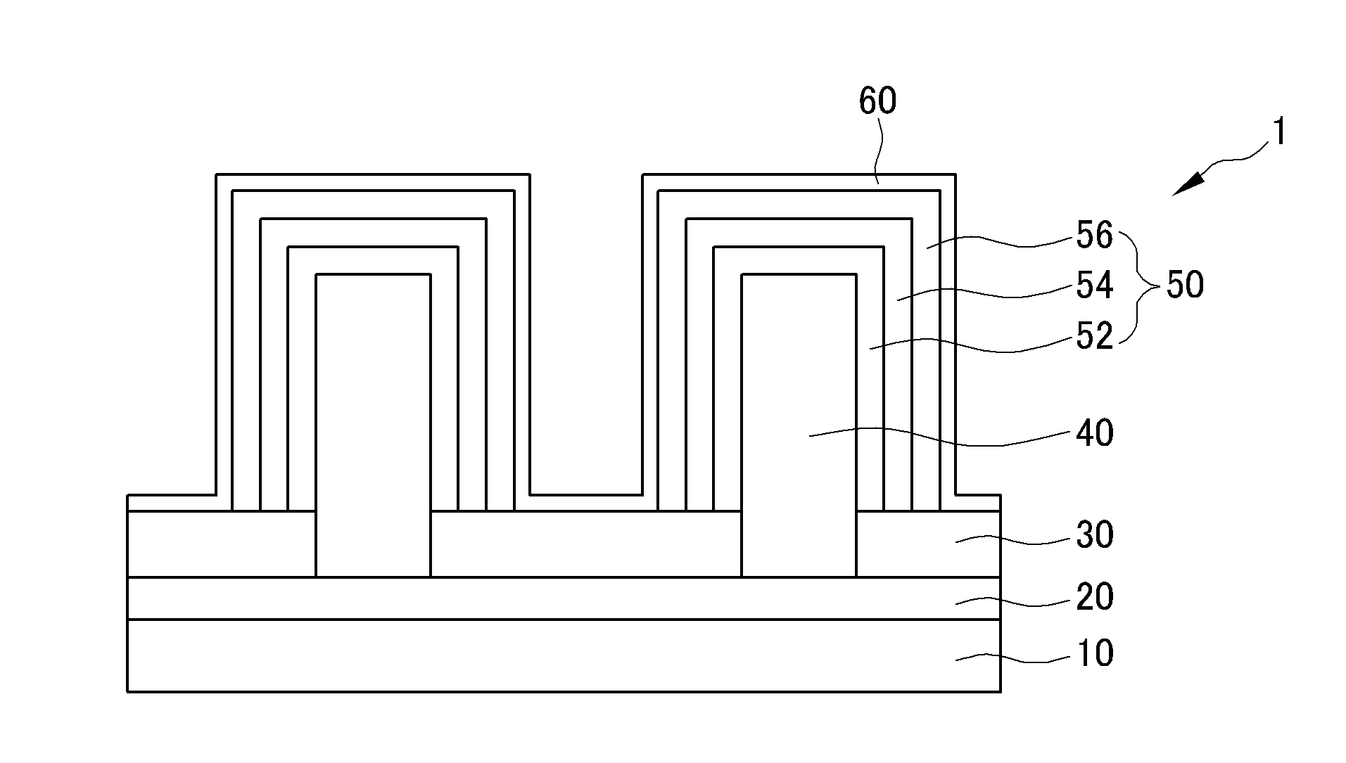
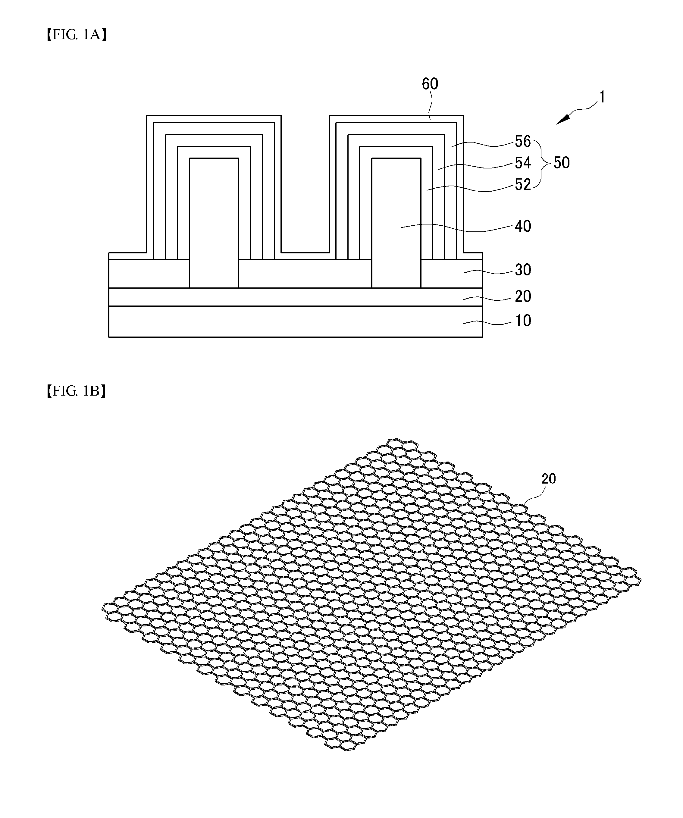
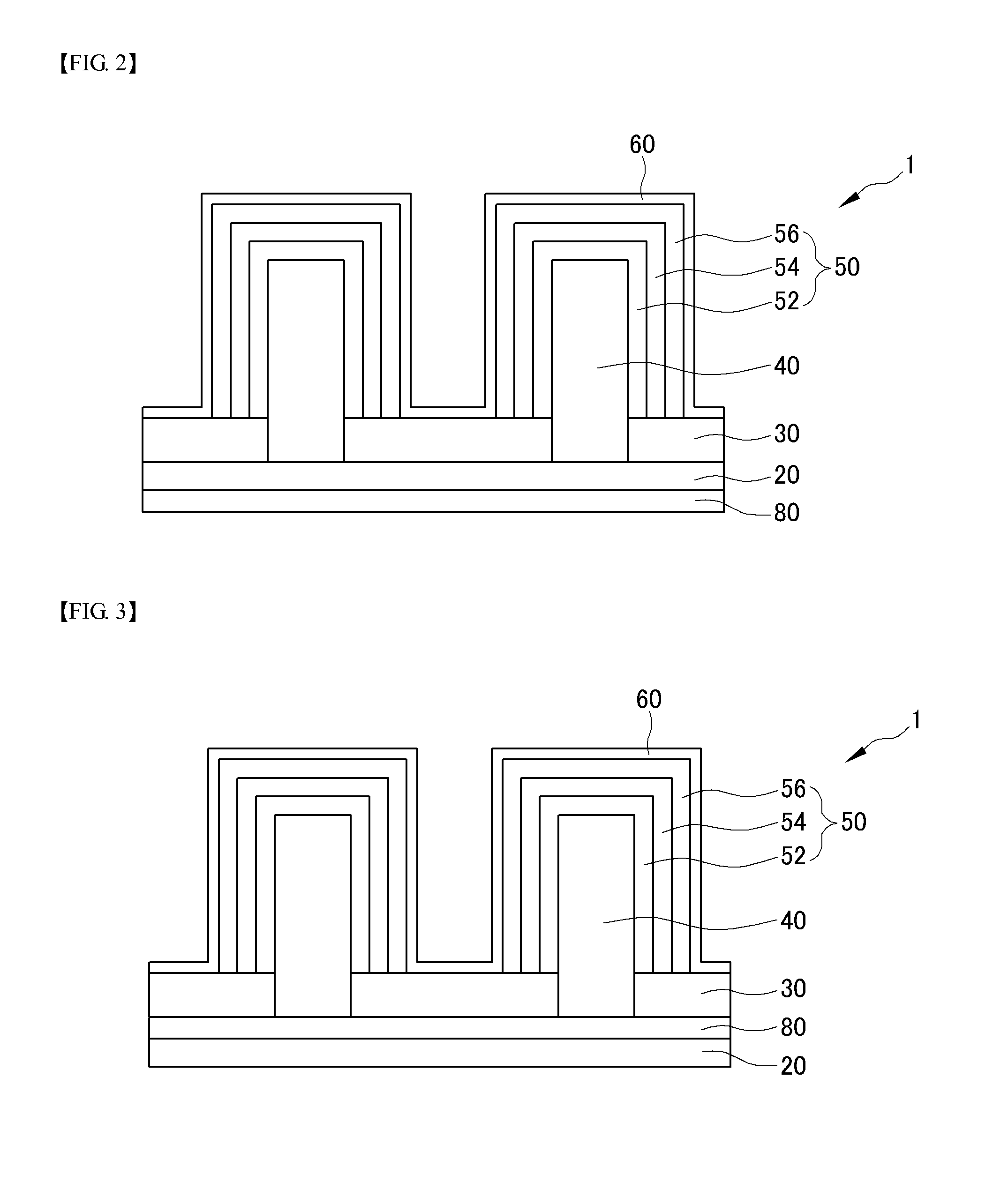
[0010]The present invention provides a light-emitting element including graphene and a method of manufacturing the same. Specifically, the present invention includes forming microstructures on graphene and forming a light-emitting structure layer on surfaces of the microstructures. As a result, it is possible to separate a light-emitting element to be transferred to a variety of substrates.
[0011]In addition, since the microstructures have excellent electrical and optical properties due to excellent crystallinity, it is possible to manufacture a high-efficiency light-emitting element. Further, since graphene has excellent electrical conductivity, it is possible to use gra

Problems solved by technology

However, although a sapphire substrate has an excellent light transmission property and mechanical strength, it also has disadvantages such as low thermal conductivity and difficulty in processing.
In spite of the above-described mer

Method used


Image

  • Light-emitting element and method for manufacturing same
  • Light-emitting element and method for manufacturing same
  • Light-emitting element and method for manufacturing same

Examples


Embodiment Construction

[0024]Various embodiments will now be described more fully with reference to the accompanying drawings in which some embodiments are shown. These present inventions may, however, be embodied in different forms and should not be construed as limited to the embodiments set forth herein. Rather, these embodiments are provided so that this disclosure is thorough and complete and fully conveys the present invention to those skilled in the art. In the drawings, the sizes and relative sizes of layers and regions may be exaggerated for clarity.

[0025]It will be understood that when an element is referred to as being “connected” or “coupled” to another element, it can be directly connected or coupled to the other element or intervening elements may be present. Further, it will be understood that when a layer (or film), a region, a pattern, or a structure is referred to as being “on” a substrate, a layer (or film), a region, a pad, or patterns, it can be directly on another layer or substrate,...


PUM


Abstract

The present invention provides a light-emitting element comprising: a carbon layer comprising a graphene; a plurality of fine structures having grown toward the upper side of the carbon layer; and a light-emitting structure layer formed on the surface of the fine structures

Description

TECHNICAL FIELD [0001]The present invention relates to a light-emitting element and a method of manufacturing the same.BACKGROUND ART [0002]A light-emitting diode (LED) is an example of a light-emitting element. An LED is a device that emits light due to electron-hole pairs near a p-n junction or in an active layer by flowing current through a terminal of a compound semiconductor. Recently, advances in semiconductor technologies have led to rapid progress in producing high-quality LEDs. For example, technologies that implement a blue LED with high brightness by forming a III-V group nitride layer on a sapphire substrate using a metal-organic chemical vapor deposition (MOCVD) method are being commercialized.[0003]As described above, a conventional LED has been manufactured by depositing a compound mainly on a sapphire substrate. However, although a sapphire substrate has an excellent light transmission property and mechanical strength, it also has disadvantages such as low thermal co...

Claims


Application Information

Patent Timeline
IPC IPC(8): H01L33/34H01L33/04
CPCB82Y20/00H01L33/08H01L33/16H01L33/18H01L33/0079H01L33/641H01L33/04H01L33/34H01L33/005H01L33/24H01L33/0093
Inventor YI, GYUCHULLEE, CHULHOKIM, YONGJIN
Owner SEOUL NAT UNIV R&DB FOUND
Why Eureka
Try Eureka