Target structure and radiation generating apparatus

a radiation generation apparatus and target technology, applied in the direction of material analysis using wave/particle radiation, instruments, x-ray tube targets and convertors, etc., can solve the problems of inapplicability of technology to transmissive targets, significant limit in the combination of materials to be used, and separation of target layers or intermediate thin films

Inactive Publication Date: 2013-08-01
CANON KK
View PDF3 Cites 48 Cited by
  • Summary
  • Abstract
  • Description
  • Claims
  • Application Information

AI Technical Summary

Benefits of technology

[0009]The present invention provides a radiation transmissive target structure having a target layer and a substrate supporting the target layer, in which separation of the target layer at an interface between the substrate and the target layer is restrained, and a radiation generating apparatus and a radiography system having such a target structure.

Problems solved by technology

Excessive temperature increases may cause thermal stress in the target layer and the supporting substrate due to the difference in coefficient of thermal expansion therebetween, and hence separation of the target layer at the interface between the target layer and the supporting substrate may result.
As described above, even if the intermediate thin film is formed between the target layer and the supporting substrate, when there is a significant difference among the coefficients of thermal expansion of respective materials of the target layer, the supporting substrate, and the intermediate thin film, separation of the target layer or the intermediate thin film may occur due to excessive and repetitive high temperature increases.
There is also a problem that when an attempt is made to equalize the coefficients of the thermal expansion of the materials of the target layer, the supporting substrate, and the intermediate thin film, combinations of the materials to be used are significantly limited.
Although the technology disclosed in U.S. Pat. No. 7,079,625 is intended to inhibit the deformation of the target layer caused by a large thickness of the target layer, this technology is not applicable for the transmissive target.

Method used


Image

  • Target structure and radiation generating apparatus
  • Target structure and radiation generating apparatus
  • Target structure and radiation generating apparatus

Examples


first embodiment

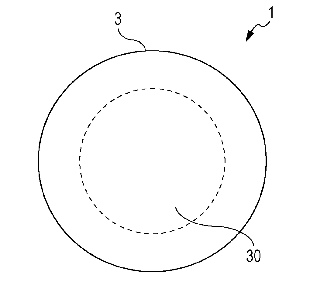
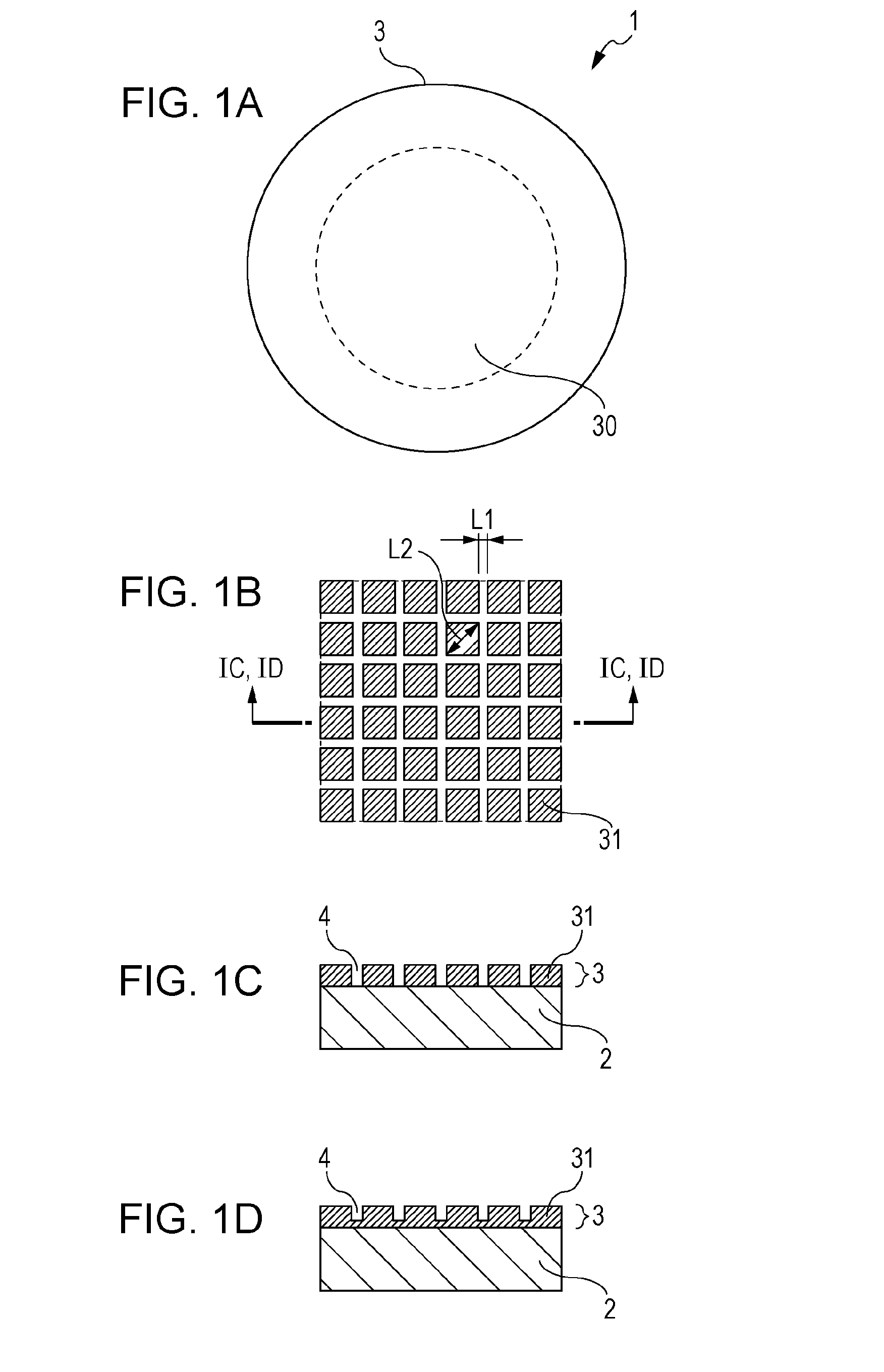
[0020]FIGS. 1A to 1D are schematic drawings illustrating a transmissive target structure of a first embodiment. FIG. 1A is a top view, FIG. 1B is an enlarged drawing of an area 30 in FIG. 1A, and FIGS. 1C and 1D are cross-sectional views taken along the line IC, ID-IC, ID in FIG. 1B.

[0021]A target structure 1 includes a substrate 2 and a target layer 3 formed on a surface of the substrate 2. When an electron beam enters the target layer 3, radiation is generated, and part of the generated radiation transmits through the substrate 2 and is emitted to the opposite side of the target layer 3.

[0022]Materials which constitute the substrate 2 can be those having strength enough for supporting the target layer 3, absorbing little radiation generated in the target layer 3, and having a high thermal conductivity so as to be capable of releasing heat generated in the target layer 3 quickly. For example, diamond, silicon carbide, silicon nitride, aluminum nitride may be used. The thickness of ...

second embodiment

[0033]FIGS. 3A and 3B are cross-sectional views of a radiation-transmissive type target structure of a second embodiment. In the second embodiment, an intermediate layer 5 is provided between the substrate 2 and the target layer 3, and other configuration may be the same as those in the first embodiment.

[0034]In FIGS. 3A and 3B, the intermediate layer 5 has a function to further improve adhesiveness between the substrate 2 and the target layer 3. The material which constitutes the intermediate layer 5 can be a material having good adhesiveness with respect to the material which constitutes the substrate 2 and the target layer 3. Examples of such materials include titanium, chrome, vanadium, tantalum, or alloy or compound containing such metals. The intermediate layer 5 may have a function to allow heat generated in the target layer 3 to be conducted to the substrate 2.

[0035]The thickness of the intermediate layer 5 can be a thickness which ensures the adhesiveness between the substr...

third embodiment

[0040]In a third embodiment, a protective layer 6 covering the target layer 3 is provided without covering the depressed portions 4 of the target layer 3, and other configurations are the same as those in the first embodiment.

[0041]In FIG. 4, the protective layer 6 is configured to restrain separation or lifting of the target layer 3, and the material of the protective layer 6 can be those having good adhesiveness with respect to the materials of the substrate 2 and the target layer 3, and having a coefficient of thermal expansion close thereto. In addition, a material having relatively small atomic numbers which have a large electron penetration depth can be sued for reducing the absorption of the electron beam in the protective layer 6. Examples of options of such materials include titanium, nickel, zirconium, chrome, niobium, silicon, or alloy or compound containing such metals. The protective layer 6 can also be formed continuously so as to cover the target layer 3 and the depre...


PUM

PropertyMeasurementUnit
thicknessaaaaaaaaaa
widthaaaaaaaaaa
widthaaaaaaaaaa

Abstract

A radiation-transmissive type target structure includes a target layer formed on a substrate. The target layer has a thickness equal to or less than 20 μm, and is configured to generate radiation in response to irradiation of electrons. A surface of the target layer is formed with projecting portions and depressed portions, the depressed portions have a depth of at least half the thickness of the target layer. Advantageously, separation of the target layer at an interface between the substrate and the target layer is substantially prevented. A radiation generating apparatus and a radiography system equipped with the target structure are also disclosed.

Description

BACKGROUND OF THE INVENTION[0001]1. Field of the Invention[0002]The present invention relates to a target structure for a radiation generating apparatus applicable to X-ray photography in the fields of medical imaging or non-destructive testing. The present invention also relates to a radiation generating apparatus and a radiography system equipped with the target structure.[0003]2. Description of the Related Art[0004]A radiation generating apparatus accelerates electrons emitted from an electron emitting source and irradiates a target structure to generate radiation. The target structure may include either a reflective target configured to extract radiation reflected from a target surface, or a transmissive target configured to extract radiation transmitting through the target structure. In both cases, when an electron beam emitted from the electron emitting source enters the target, a large part of incident energy is converted into heat. For this reason, the temperature of the tar...

Claims


Application Information

Patent Timeline
Patent Type & Authority Applications(United States)
IPC IPC(8): H01J35/08G01N23/04
CPCH01J35/12H01J2235/084G01N23/04H01J35/08H01J2235/087H01J35/116
Inventor TAMURA, MIKISATO, YASUEYAMAZAKI, KOJI
Owner CANON KK
Why Eureka
Try Eureka