Systems and methods for percutaneous electrical stimulation

a technology percutaneous electrode, applied in the field of percutaneous electrical stimulation, can solve the problems of difficult to meet the needs of patients, etc., and achieve the effect of not being mated easily

Inactive Publication Date: 2013-08-01
NDI MEDICAL
View PDF4 Cites 85 Cited by
  • Summary
  • Abstract
  • Description
  • Claims
  • Application Information

AI Technical Summary

Benefits of technology

[0010]According to one aspect of one or more embodiments according to the present invention, a small electrical stimulator is provided having controls and a user output interface, such as a liquid crystal display (LCD), that allows the use by a patient (likely daily use), preferably without complicated interaction by a user patient other than attaching the stimulator to a mounting patch, connecting a cable to a percutaneous lead, and turning the stimulator on. A stimulator according to the present invention preferably also allows the programming of stimulus parameters by a clinician without the use of any additional equipment, though separate clinician programming equipment is contemplated.
[0011]According to another aspect of one or more embodiments according to the present invention, a stimulator may be electrically and mechanically mounted to a patch assembly that may serves as both a surface return electrode for the stimulus current and also as the power source for stimulation. The connection of the stimulator to the surface electrode assembly is preferably in the form of two simple snaps that can be mated and unmated easily in either polarity (orientation) without fear of device damage or user injury.

Problems solved by technology

While existing systems and methods can provide remarkable benefits to individuals requiring neurostimulation, many quality of life issues still remain.
For example, existing systems are, by today's standards, relatively large and awkward to manipulate and transport.
Prior stimulators have utilized distinct mounting structure and power sources and have not provided convenient mechanisms for ensuring proper lead placement or adjustment of stimulation parameters.
Several clinical and technical issues associated with surface electrical stimulation have prevented it from becoming a widely accepted treatment method.
First, stimulation of cutaneous pain receptors often cannot be avoided resulting in stimulation-induced pain that limits patient tolerance and compliance.
Second, electrical stimulation is delivered at a relatively high frequency to prevent stimulation-induced pain, which leads to early onset of muscle fatigue.
Third, it is difficult to stimulate deep muscles with surface electrodes without stimulating overlying, more superficial muscles resulting in unwanted stimulation.
The required daily maintenance and adjustment of a surface electrical stimulation system is a major burden on both patient and caregiver.

Method used


Image

  • Systems and methods for percutaneous electrical stimulation
  • Systems and methods for percutaneous electrical stimulation
  • Systems and methods for percutaneous electrical stimulation

Examples


embodiment 200

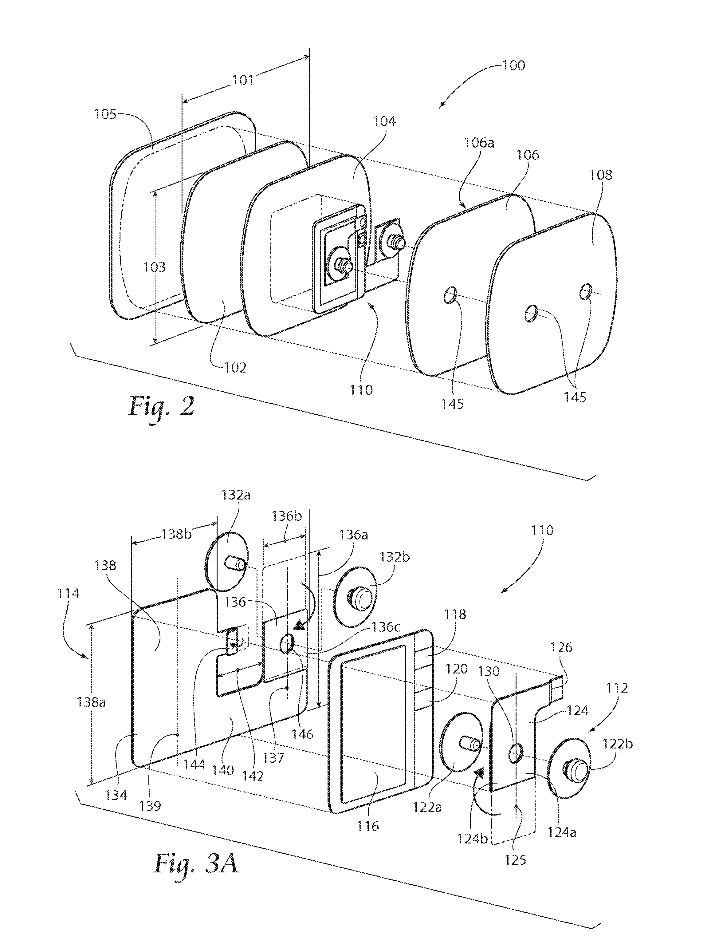
[0055]Turning now to FIGS. 4A-5, an embodiment 200 of an electrical stimulator according to the present invention may be described. Generally, the stimulator 200 includes a housing 201 having a cover 202 and a base 204. The housing 201 generally forms a cavity 203 that is configured to at least partially contain a printed circuit board 206 on which electrical stimulation generation circuitry may be mounted. Generally, the housing 201 extends between and includes a front surface 208 and an opposed back surface 210, a top surface 212 and an opposed bottom surface 214, and a left surface 216 and an opposed right surface 218. The housing 201 may have a plurality of apertures or passageways 205 formed therethrough, allowing access to the cavity 203, either functionally or physically. Functional access may be provided to a user output interface, such as a display screen 220, or to a user input interface, such as one or more buttons or keys 222a,222b,222c,222d. Physical and / or functional a...

embodiment 300

[0088]FIGS. 9-11 depict various cable embodiments 300 according to the present invention. A first cable embodiment 300, shown in FIG. 9, generally includes a single conductive path extending between and including a first connector element 302 and a second conductor element 304. The first connector element 302 is preferably a touchproof pin connector having a conductive pin of a first diameter, such as about 1.0 millimeter. The second connector element 304 is preferably also a touchproof pin connector having a conductive pin of a second diameter, which is preferably different from the first diameter, such as being greater than the first diameter. The second diameter is preferably about 1.5 millimeters. The provision of different connector pin diameters is preferred to aid in preventing reversal of the cable 300 during use. Additionally, the first connector element 302 may be provided as a first color, such as a color that corresponds to a color of the stimulator housing 201, such as ...


PUM

PropertyMeasurementUnit
timeaaaaaaaaaa
thicknessaaaaaaaaaa
thicknessaaaaaaaaaa

Abstract

Systems and methods according to the present invention relate to a substantially extracorporeal pulse generator system for electrical stimulation of one or more target nerve or their branches using one or more preferably percutaneous leads each having one or more electrodes implanted in, on, around, or near the target nerve. Improved systems include a patch assembly configured to be adhesively mounted to a patient's skin and an electrical stimulation assembly configured to be mechanically mounted to the patch assembly. A preferred patch assembly, in addition to provide mechanical mounting of the stimulation assembly, provides a power source for the stimulation assembly, and may further serve as a return electrode. Associated system components and methods of use are also provided.

Description

RELATED APPLICATIONS[0001]This application is a continuation of co-pending U.S. patent application Ser. No. 13 / 323,152 filed 12 Dec. 2011, which is a continuation of application Ser. No. 13 / 095,616, filed Apr. 27, 2011, which claimed the benefit of U.S. Provisional Patent Application Ser. No. 61 / 343,325, filed Apr. 27, 2010, and entitled “Systems and Methods for Percutaneous Electrical Stimulation,” each of which is incorporated herein by reference in its entirety.BACKGROUND OF THE INVENTION[0002]This invention relates generally to the field of electrical stimulation and more particularly to systems and methods for providing improved percutaneous electrical stimulation of nerves and / or muscles.[0003]Neurostimulation, i.e., neuromuscular stimulation (the electrical excitation of nerves and / or muscle that may directly elicit the contraction of muscles) and neuromodulation stimulation (the electrical excitation of nerves, often afferent nerves, to indirectly affect the stability or per...

Claims


Application Information

Patent Timeline
Patent Type & Authority Applications(United States)
IPC IPC(8): A61N1/05H01R43/00
CPCA61N1/0492A61N1/0502A61N1/36017Y10T29/49117A61N1/0504H01R43/00A61N1/36021
Inventor RUNDLE, KENNETH P.GALECKI, STEVEN M.MARKS, MICHAELMRVA, JOSEPH J.SAKAI, JONATHAN L.STROTHER, ROBERT B.
Owner NDI MEDICAL
Why Eureka
Try Eureka