Method for manufacturing hot stamped body having vertical wall and hot stamped body having vertical wall

a technology of hot stamping body and vertical wall, which is applied in the direction of manufacturing tools, heat treatment equipment, furnaces, etc., can solve the problems of uneven microstructure of hot-rolled sheet after hot-rolling step, difficult to achieve spheroidizing of carbide to realize softness and evenness of steel sheet by long-time thermal treatment such as batch treatment, etc., to achieve the effect of stabilizing the hardness of hot-rolled body

Active Publication Date: 2013-08-08
NIPPON STEEL CORP
View PDF0 Cites 14 Cited by
  • Summary
  • Abstract
  • Description
  • Claims
  • Application Information

AI Technical Summary

Benefits of technology

[0044]According to the methods according to (1) to (8) described above, since the steel sheet in which physical properties after the annealing are even and soft is used, even when manufacturing a formed body having a vertical wall from such a steel sheet by hot stamping, it is possible to stabilize hardness of the hot stamped body.
[0045]In addition, by performing a hot-dip galvanizing process, a galvannealing process, a molten aluminum plating process, an alloyed molten aluminum plating process, or an electroplating process, after the continuous annealing step, it is advantageous since it is possible to prevent scale generation on a surface, raising a temperature in a non-oxidation atmosphere for avoiding scale generation when raising a temperature of hot stamping is unnecessary, or a descaling process after the hot stamping is unnecessary, and also, rust prevention of the hot stamped body is exhibited.
[0046]In addition, by employing such methods, it is possible to obtain a hot stamped body having a vertical wall in which, when a quenching start temperature is equal to or lower than 650° C., variation of Vickers hardness ΔHv of the hot stamped body is equal to or less than 100, when the quenching start temperature is 650° C. to 750° C., variation of Vickers hardness ΔHv of the hot stamped body is equal to or less than 60, and when the quenching start temperature is equal to or higher than 750° C., variation of Vickers hardness ΔHv of the hot stamped body is equal to or less than 40.

Problems solved by technology

However, although the strength and the hardenability are properties necessary for a hot stamped product, when manufacturing a steel sheet which is a material thereof, these properties are disadvantageous, in many cases.
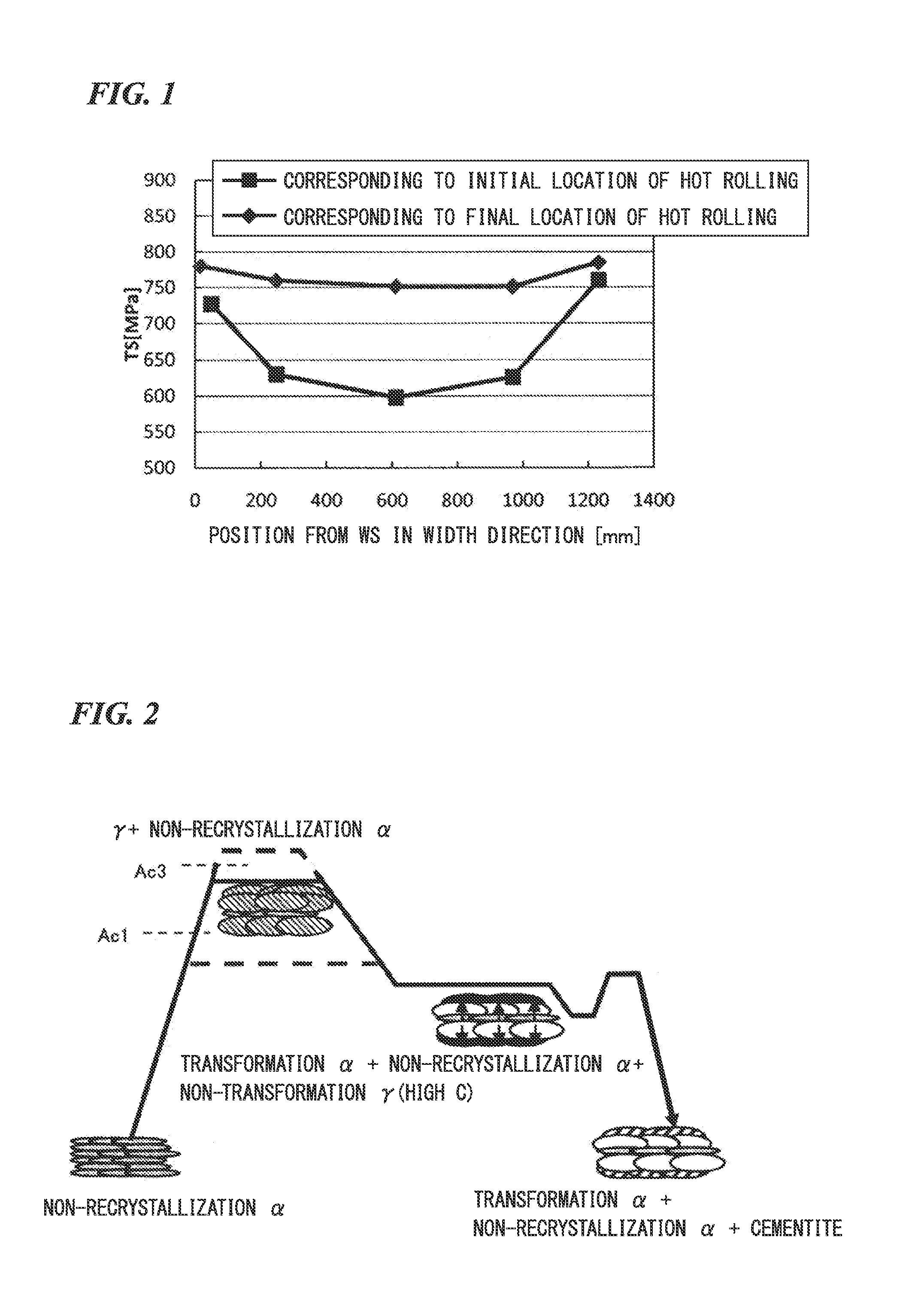
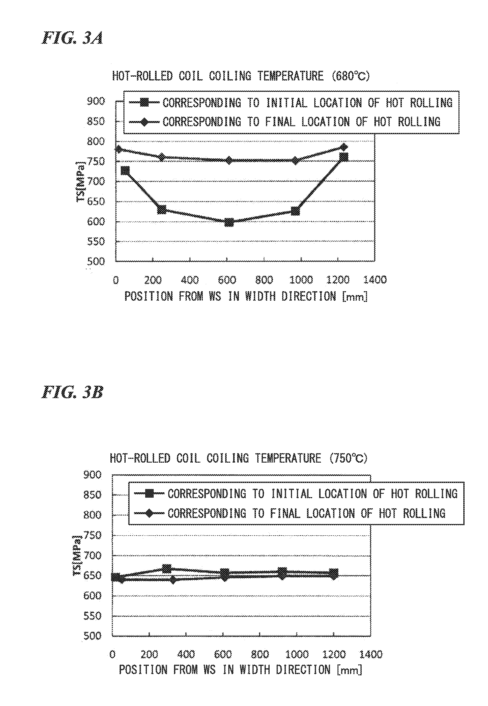
As a representative disadvantage, with a material having such a high hardenability, a hot-rolled sheet after a hot-rolling step tends to have an uneven microstructure in locations in hot-rolled coil.
However, in a case of the continuous annealing step, since the annealing time is short, it is difficult to perform spheroidizing of carbide to realize softness and evenness of a steel sheet by long-time thermal treatment such as a batch treatment.
On the other hand, in a case of a short-time thermal treatment such as the continuous annealing step, it is difficult to secure the annealing time necessary for the spheroidizing.
However, a heating method of a hot stamping material by the furnace heating has poor productivity since the heating takes a long time.
As the hot stamping material, this not only becomes a reason for die abrasion in a blank before stamping, but also significantly decreases formability or shape fixability of a formed body.
However, if considering manufacturing cost as a priority and assuming the manufacture of the steel sheet in a continuous annealing installation, it is difficult to perform the control described above by an annealing technology of the related art.
Accordingly, since variation in hardness generated when quenching is added with respect to the variation in hardness in the steel sheet before heating in a hot stamping step, there is a problem in that significant variation in hardness is generated in the formed body having the vertical wall.

Method used


Image

  • Method for manufacturing hot stamped body having vertical wall and hot stamped body having vertical wall
  • Method for manufacturing hot stamped body having vertical wall and hot stamped body having vertical wall
  • Method for manufacturing hot stamped body having vertical wall and hot stamped body having vertical wall

Examples


first embodiment

[0117]Hereinafter, a method for manufacturing a hot stamped body having a vertical wall according to a first embodiment of the present invention will be described.

[0118]The method for manufacturing a hot stamped body having a vertical wall according to the embodiment includes at least a hot-rolling step, a coiling step, a cold-rolling step, a continuous annealing step, and a hot stamping step. Hereinafter, each step will be described in detail.

[0119](Hot-Rolling Step)

[0120]In the hot-rolling step, a steel piece having the chemical components described above is heated (re-heated) to a temperature of equal to or higher than 1100° C., and the hot-rolling is performed. The steel piece may be a slab obtained immediately after being manufactured by a continuous casting installation, or may be manufactured using an electric furnace. By heating the steel piece to a temperature of equal to or higher than 1100° C., carbide-forming elements and carbon can be subjected to decomposition-dissolvi...

second embodiment

[0142]Hereinafter, a method for manufacturing the hot stamped body having a vertical wall according to a second embodiment of the present invention will be described.

[0143]The method for manufacturing a hot stamped body according to the embodiment includes at least a hot-rolling step, a coiling step, a cold-rolling step, a continuous annealing step, and a hot stamping step. Hereinafter, each step will be described in detail.

[0144](Hot-Rolling Step)

[0145]In the hot-rolling step, a steel piece having the chemical components described above is heated (re-heated) to a temperature of equal to or higher than 1100° C., and the hot-rolling is performed. The steel piece may be a slab obtained immediately after being manufactured by a continuous casting installation, or may be manufactured using an electric furnace. By heating the steel piece to a temperature of equal to or higher than 1100° C., carbide-forming elements and carbon can be subjected to decomposition-dissolving sufficiently in t...

examples

[0172]Next, Examples of the present invention will be described.

TABLE 1CMnSiPSNAlTiBCrAc1Ac3DIinchSteel type(mass %)(° C.)(° C.)—A0.221.350.150.0090.0040.0030.0100.0200.00120.227358504.8B0.221.650.030.0090.0040.0040.0100.0100.00130.027258403.5C0.221.950.030.0080.0030.0030.0100.0120.00130.157258304.2D0.232.130.050.0100.0050.0040.0200.0150.00150.107208255.2E0.281.850.100.0080.0040.0030.0150.0800.00130.017258253.8F0.241.630.850.0090.0040.0030.0320.0200.00140.017408605.4G0.212.620.120.0080.0030.0030.0220.0150.00120.107258208.0H0.161.540.300.0080.0030.0030.0200.0120.00100.037358503.4I0.401.640.200.0090.0040.0040.0100.0200.00120.017308104.1J0.210.820.130.0070.0030.0030.0210.0200.00110.017358651.8K0.283.820.130.0080.0030.0040.0200.0100.00120.137107707.1L0.261.851.320.0080.0040.0030.0200.0120.00150.017558809.2M0.291.500.300.0080.0030.0041.3000.0200.00180.0173510554.6N0.241.300.030.0080.0040.0030.0200.3100.00120.207308504.1O0.221.800.040.0090.0050.0030.0100.0200.00010.107258302.2P0.231.600.0...


PUM

PropertyMeasurementUnit
temperatureaaaaaaaaaa

Abstract

The present invention provides a method for manufacturing a hot stamped body having a vertical wall, the method including: a hot-rolling step; a coiling step; a cold-rolling step; a continuous annealing step; and a hot stamping step, in which the continuous annealing step includes a heating step of heating the cold-rolled steel sheet to a temperature range of equal to or higher than Ac1° C. and lower than Ac3° C.; a cooling step of cooling the heated cold-rolled steel sheet from the highest heating temperature to 660° C. at a cooling rate of equal to or less than 10° C./s; and a holding step of holding the cooled cold-rolled steel sheet in a temperature range of 550° C. to 660° C. for one minute to 10 minutes.

Description

TECHNICAL FIELD[0001]The present invention relates to a method for manufacturing a hot stamped body having a vertical wall and a hot stamped body having a vertical wall.[0002]Priority is claimed on Japanese Patent Application No. 2010-237249, filed Oct. 22, 2010, the content of which is incorporated herein by reference.BACKGROUND ART[0003]In order to obtain high-strength components of a grade of 1180 MPa or higher used for automobile components or the like with excellent dimensional precision, in recent years, a technology (hereinafter, referred to as hot stamping forming) for realizing high strength of a formed product by heating a steel sheet to an austenite range, performing pressing in a softened and high-ductile state, and then rapidly cooling (quenching) in a press die to perform martensitic transformation has been developed.[0004]In general, a steel sheet used for hot stamping contains a lot of C component for securing product strength after hot stamping and contains austenit...

Claims


Application Information

Patent Timeline
Patent Type & Authority Applications(United States)
IPC IPC(8): C21D8/02
CPCC21D9/46C22C38/26C22C38/001C22C38/02C22C38/06C22C38/28C22C38/32C22C38/38C21D8/0263C21D8/0226C21D8/0236C21D8/0273C22C38/48C22C38/46C22C38/44C22C38/42C22C38/40C22C38/58C22C38/24C22C38/20C21D8/005C22C38/54C22C38/50C21D2211/005
Inventor TOMOKIYO, TOSHIMASAHAYASHI, KUNIOASO, TOSHIMITSU
Owner NIPPON STEEL CORP
Why Eureka
Try Eureka