Front-End System for Radio Devices

a radio device and front-end technology, applied in the direction of different amplifiers, amplifiers with semiconductor devices/discharge tubes, low noise amplifiers, etc., can solve the problems of introducing noise figures, affecting the performance of the amplifier, and difficult to achieve noise figures less than 7 db using proposed solutions, etc., to achieve low power, cost and area effective

Active Publication Date: 2013-08-22
INTERUNIVERSITAIR MICRO ELECTRONICS CENT (IMEC VZW)
View PDF20 Cites 11 Cited by
  • Summary
  • Abstract
  • Description
  • Claims
  • Application Information

AI Technical Summary

Benefits of technology

[0011]The present disclosure aims at providing a low power, cost and area effective front-end system for wireless devices operating at mm-waves.
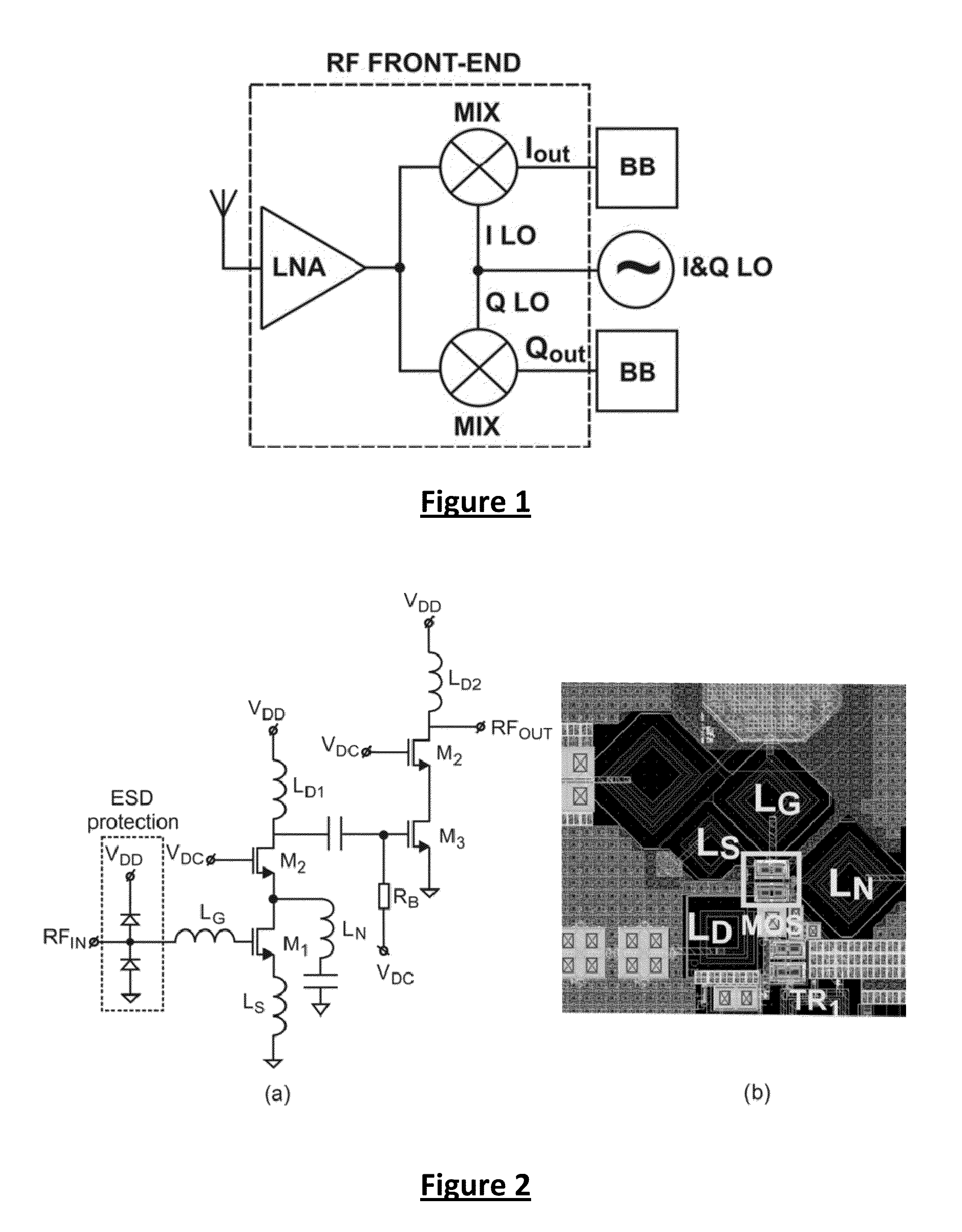
[0018]In another embodiment, the first amplification stage comprises a resistive shunt feedback circuit, whereby the resistive shunt feedback circuit further comprises a capacitor connected in series to a resistor, for DC decoupling the low-noise amplifier. The simultaneous use of neutralization circuit and a resistive shunt feedback circuit with capacitor helps achieving simultaneously low noise figure, good impedance match and improved stability of the low-noise amplifier.

Problems solved by technology

For a radio receiver operating at millimetre-waves the most challenging tasks are the design and implementation of the blocks operating directly at the radio frequency, i.e. so called radio frequency (RF) building blocks.
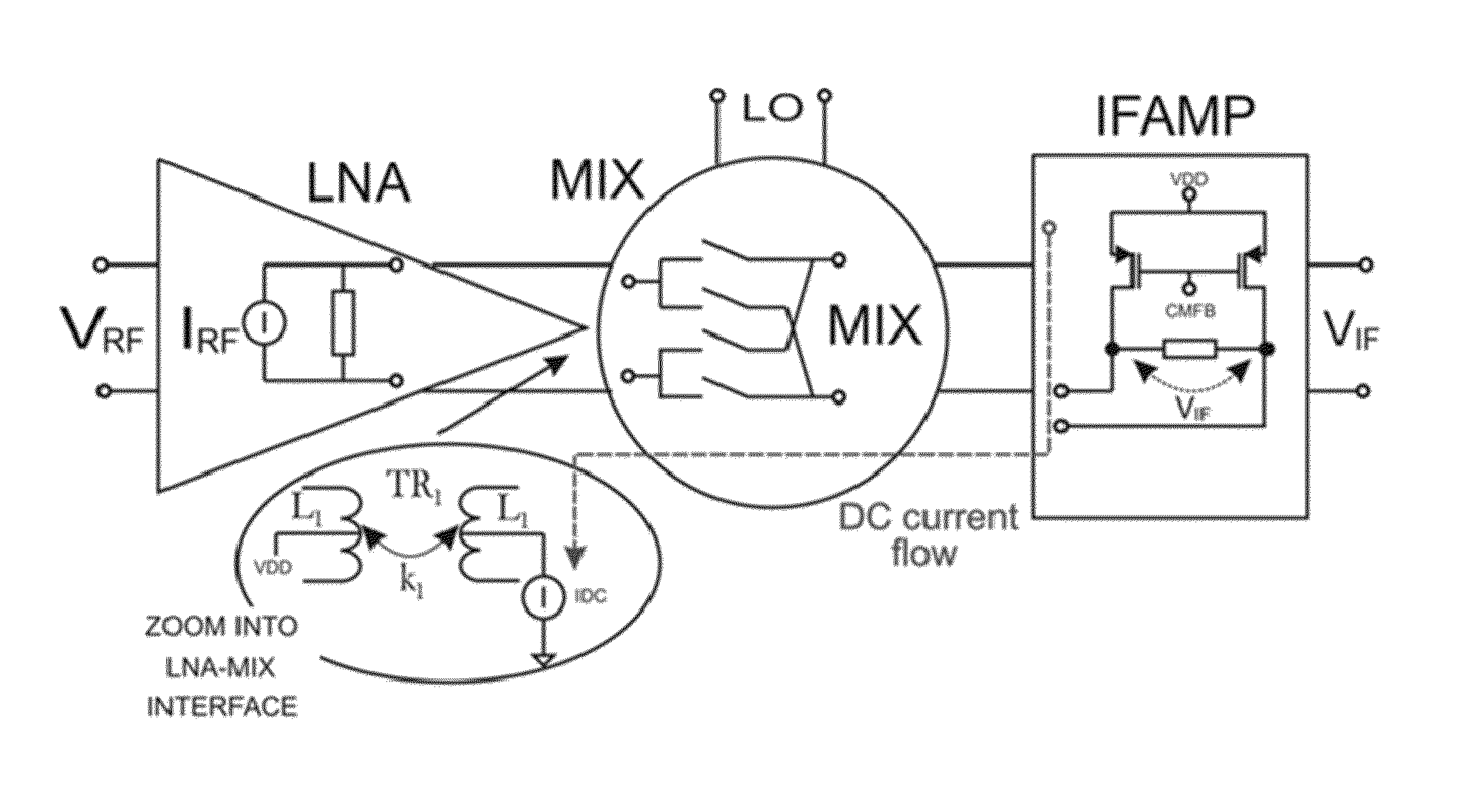
The design challenge comes from the fact that the RF front-end (i.e. the LNA and MIX blocks) are tuned circuits, which intensively use inductive passive elements (inductors or transformers) to tune out / cancel parasitic capacitances.
In addition, since the RF building blocks operate directly at mm-wave frequencies, they represent the most power hungry part of a radio receiver as well as the strongest noise contributor.
However, there are a couple of problems associated with the proposed solutions.
First, the layout is bulky because they use several inductors per stage.
Second, the ESD protection, which is made by using diodes, introduces penalty to the noise figure.
It is difficult to achieve noise figure lower than 7 dB using proposed solutions.
Further, these conventional architectures suffer from high current losses as they use current-commutating mixer.
The presented feedback configurations simply cannot be used at 60 GHz because the active element (amplifier) cannot provide sufficient gain.

Method used


Image

  • Front-End System for Radio Devices
  • Front-End System for Radio Devices
  • Front-End System for Radio Devices

Examples


Embodiment Construction

[0036]The present invention will be described with respect to particular embodiments and with reference to certain drawings but the invention is not limited thereto. The drawings described are only schematic and are non-limiting. In the drawings, the size of some of the elements may be exaggerated and not drawn on scale for illustrative purposes. The dimensions and the relative dimensions do not necessarily correspond to actual reductions to practice of the invention.

[0037]Furthermore, the terms first, second, third and the like in the description and in the claims, are used for distinguishing between similar elements and not necessarily for describing a sequential or chronological order. The terms are interchangeable under appropriate circumstances and the embodiments of the invention can operate in other sequences than described or illustrated herein.

[0038]Moreover, the terms top, bottom, over, under and the like in the description and the claims are used for descriptive purposes ...


PUM


Abstract

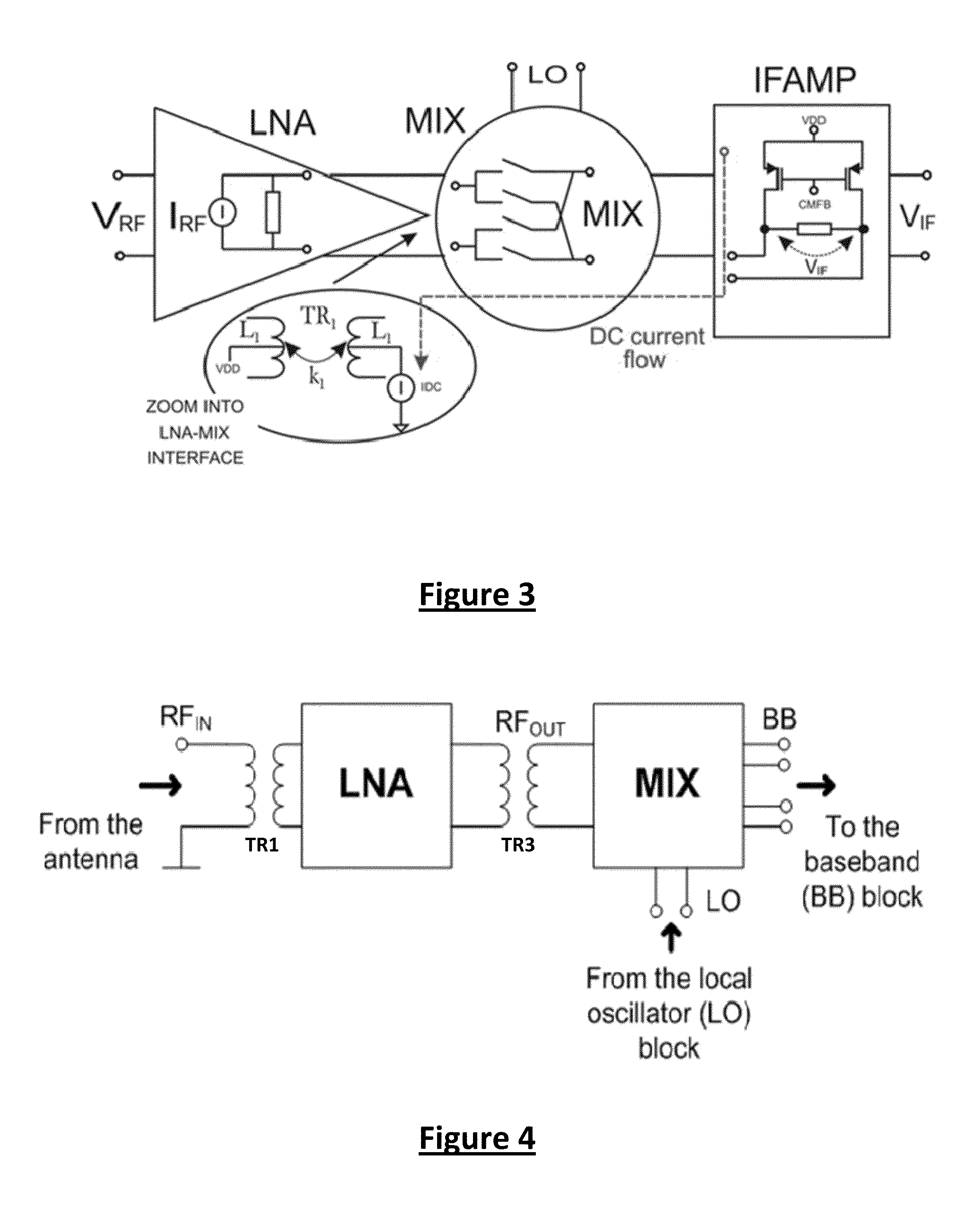
The present disclosure relates to a front-end system for a radio device, the front-end system comprising a low-noise amplifier (LNA), arranged for receiving a radio frequency input signal (RFIN) and arranged for outputting an amplified radio frequency signal (RFOUT), wherein the low-noise amplifier comprises a first differential amplifier, and a mixer (MIX), arranged for down-converting the amplified radio signal (RFOUT) provided by the low-noise amplifier (LNA) to a baseband signal (BB), by multiplying the amplified radio signal (RFOUT) with a local oscillator (LO) frequency tone, said low-noise amplifier (LNA) and said mixer (MIX) being inductively coupled.

Description

CROSS-REFERENCE TO RELATED APPLICATION[0001]This application claims priority to European Patent Application No. 12156098.1 filed on Feb. 17, 2012, the contents of which are hereby incorporated by reference.FIELD OF THE INVENTION[0002]The present disclosure relates to a front-end system for wireless devices and more specifically for wireless devices for mm-wave applications.BACKGROUND OF THE INVENTION[0003]For wireless communication at data rates above about 1 Gbit / s, a frequency band of about 7 GHz has been allocated around about 60 GHz. In this frequency band several applications are targeted with mass-market potential. For example wireless High Definition Multi-media Interface (HDMI), wireless Universal Serial Bus (USB) or SYNC-and-GO, allowing fast data download, are very interesting application for the consumer market. For wireless consumer products, the key elements are low price and low power consumption. Considering possible implementation technology, CMOS is preferred as it ...

Claims


Application Information

Patent Timeline
Patent Type & Authority Applications(United States)
IPC IPC(8): H03F3/45
CPCH03F3/45071H04B1/30H03F2200/541H03F2200/294H03F2200/141H03F2200/537H03F2200/534H03F2200/144H04B1/18
Inventor VIDOJKOVIC, VOJKANVAESEN, KRISTOFWAMBACQ, PIET
Owner INTERUNIVERSITAIR MICRO ELECTRONICS CENT (IMEC VZW)
Why Eureka
Try Eureka