
Holographic memory reproduction device and holographic memory reproduction method, demodulation device and demodulation method, and observation device and observation method

a holographic memory and reproduction device technology, applied in the field of reproduction apparatus and holographic memory reproduction method, can solve the problems of two-dimensional recording-type optical memories that have already reached diffraction limits, the probability of realizing high density recording exceeding diffraction limits, and the inability to increase capacity. achieve the effect of high degree of accuracy

Active Publication Date: 2013-08-22
HOKKAIDO UNIVERSITY
View PDF7 Cites 25 Cited by
  • Summary
  • Abstract
  • Description
  • Claims
  • Application Information

AI Technical Summary

Benefits of technology

The present invention relates to a holographic memory reproduction apparatus and method that can accurately reproduce m value phase information without being influenced by noise. This enables high accuracy in reproducing holographic memories where spatial phase modulation or quadrature amplitude modulation signals are recorded. Additionally, the present invention is about a demodulation apparatus and method that can accurately demodulate the same signals. This invention can even allow for real-time observation of light intensity and phase distribution in transmitted or reflected light from an object being observed.

Problems solved by technology

However, two-dimensional recording-type optical memories have already reached a diffraction limit, and thus a further increase in capacity is not likely to be achieved.
The near-field optical recording system is basically a two-dimensional recording-type technique, but has the likelihood of realizing high density recording exceeding a diffraction limit by using near-field light.
However, there has been a problem in the phase modulation-type holographic memory in that since a phase modulation signal cannot be directly detected in a light detector, the phase modulation signal has to be converted into an intensity signal by some kind of method and then be detected.
However, there is a problem in that, the intensity modulation has an advantage of being able to construct a system through a simple optical system, whereas the exposure intensity difference between a central portion and a peripheral portion of a laser light irradiation region becomes large, and the dynamic range of a recording medium is consumed to a large extent, thereby resulting in the deterioration of recording efficiency.
This problem is caused by the increasing exposure intensity difference between the central vicinity and the peripheral portion of the laser light irradiation region because the intensity in the vicinity of the center of a Fourier transform image is proportional to the sum of the amplitudes of all pixels in a general Fourier transform hologram (see, for example, Non-Patent Literature 4).
This means that the recording capacity per block in a case where the modulation code is used, in principle, falls short of the recording capacity in a case where the modulation code is not used.
However, in a current direct detection system, the signal-to-noise ratio of a reproduction light beam is greatly deteriorated with an increase in the multi-valued number due to the accuracy or noise of the detection system (see, for example, Non-Patent Literature 7).
However, since a photoelectric conversion device such as a CCD is sensitive only to the intensity of light, the device cannot detect phase information directly.
In the phase modulation system, this point becomes a serious problem.
There is a problem in that, this method has an advantage of being able to realize a phase modulation-type holographic memory in an optical system which is no different from an intensity modulation-type holographic memory, whereas the method is not adequate to the detection of a multi-valued phase modulation signal.
However, even in this method, there is a problem in that a multi-valued signal is not easily detected, and that the higher-accuracy design of the birefringent medium is required.
This can cause the occurrence of a phase error in a detection surface.
This method is also not likely to record and reproduce the phase information with a high degree of accuracy, and the phase multi-valued number remains in two-valued to four-valued number.

Method used


Image

  • Holographic memory reproduction device and holographic memory reproduction method, demodulation device and demodulation method, and observation device and observation method
  • Holographic memory reproduction device and holographic memory reproduction method, demodulation device and demodulation method, and observation device and observation method
  • Holographic memory reproduction device and holographic memory reproduction method, demodulation device and demodulation method, and observation device and observation method

Examples


embodiment 1

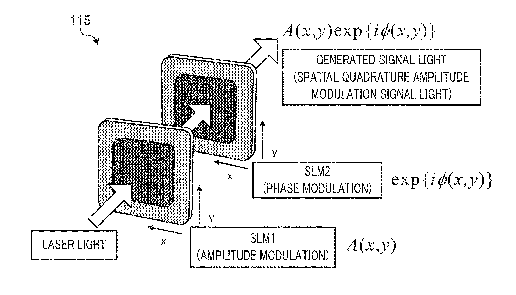
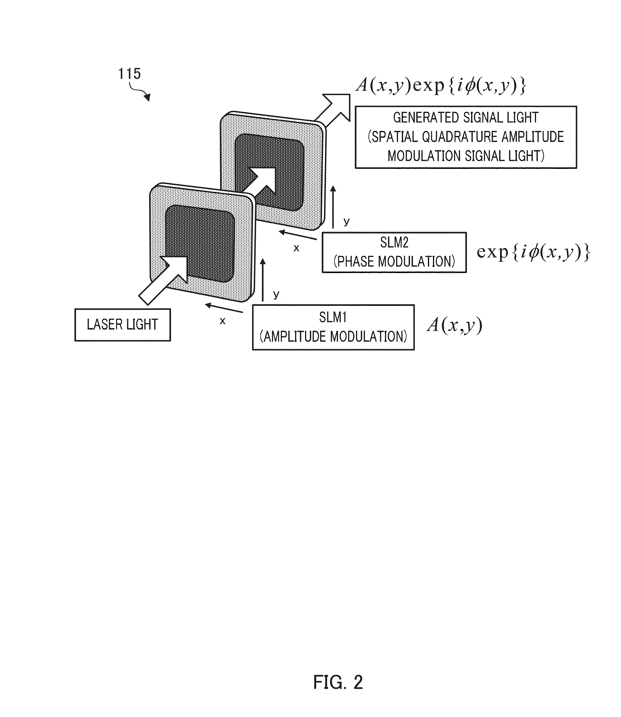
[0128]In Embodiment 1, a description will be made of a holographic memory recording and reproduction apparatus which is capable of recording a data page (two-dimensional data) in a holographic memory using signal light (spatial quadrature amplitude modulation signal light) produced with a combination of amplitude modulation and phase modulation, and reproducing the recorded data page from the holographic memory.

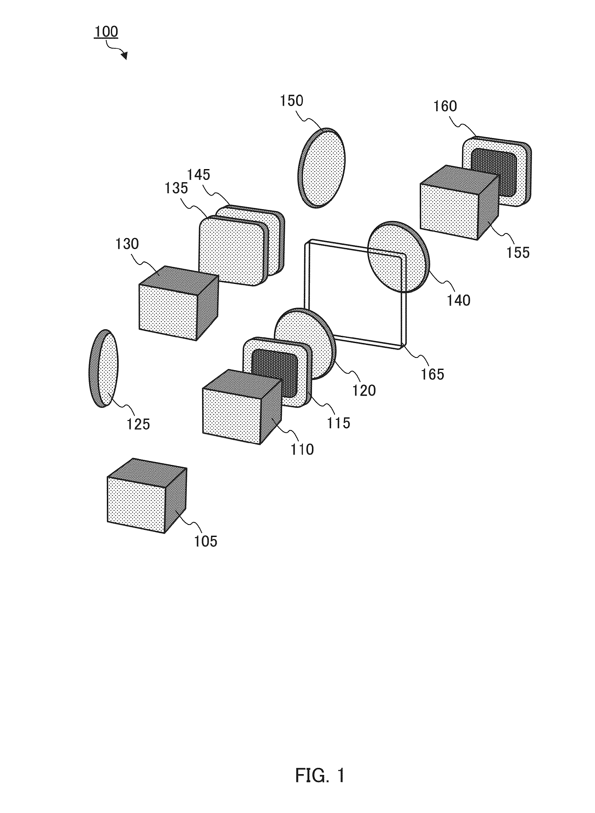
[0129]FIG. 1 is a schematic diagram illustrating a configuration of a holographic memory recording and reproduction apparatus according to Embodiment 1. As shown in FIG. 1, holographic memory recording and reproduction apparatus 100 according to Embodiment 1 includes laser light source 105, first beam splitter 110, spatial quadrature amplitude modulation signal light production section 115, first lens 120, first mirror 125, second beam splitter 130, optical shutter 135, second lens 140, variable phase shifter 145, second mirror 150, third beam splitter 155, CCD 160 and a proc...

embodiment 2

[0175]In Embodiment 1, the phase of the second reference light is changed using the variable phase shifter at the time of producing M second holograms. In Embodiment 2, a description will be made of a holographic memory recording and reproduction apparatus that simultaneously produces M second holograms without using the variable phase shifter by using a special interferometer.

[0176]In the holographic memory recording and reproduction apparatus of Embodiment 2, each component except for the hologram production section and the detection section is the same as that of the holographic memory recording and reproduction apparatus of Embodiment 1. Consequently, only the hologram production section and detection section will be described. Herein, the configurations of the hologram production section and the detection section of the holographic memory recording and reproduction apparatus of Embodiment 2 when the following equation is established as an example are shown in FIG. 6.

M=4,ΔΨ=π / 2 ...

embodiment 3

[0198]In Embodiment 2, it is necessary to adjust the optical path length between each of the beam splitters. In Embodiment 3, a description will be made of a holographic memory recording and reproduction apparatus that simultaneously produces M second holograms without adjusting the optical path length between each of the beam splitters.

[0199]In the holographic memory recording and reproduction apparatus of Embodiment 3, each component except for the hologram production section and the detection section is the same as that of the holographic memory recording and reproduction apparatus of Embodiment 1. Consequently, only the hologram production section and detection section will be described.

[0200]FIG. 8 is a schematic diagram illustrating a configuration of the hologram production section and the detection section of the holographic memory recording and reproduction apparatus according to Embodiment 3.

[0201]As shown in FIG. 8, the hologram production section and detection section in...


PUM


Abstract

The present invention relates to a reproduction device of a holographic memory capable of precisely reproducing multi-value phase information without being influenced by noise. This holographic memory reproduction device comprises: a hologram diffraction ray generation unit which irradiates a first reference ray to the holographic memory and generates a diffraction ray of the first hologram; a hologram generation unit which changes the phase of a second reference ray which may interfere with the diffraction ray of the first hologram and generates a second hologram from the diffraction ray of the first hologram and the second reference ray to which the phase has been changed; a detection unit which detects the intensity distribution of the second hologram; and a processing unit which demodulates the phase modulation signal or the space quadrature amplitude modulation signal on the basis of the intensity distribution.

Description

TECHNICAL FIELD[0001]The present invention relates to a reproduction apparatus and a reproduction method of a holographic memory. In addition, the present invention relates to a demodulation apparatus and a demodulation method of a spatial phase modulation signal or a spatial quadrature amplitude modulation signal. In addition, the present invention relates to an observation apparatus and an observation method of a light intensity distribution and a light phase distribution.BACKGROUND ART[0002]Hitherto, optical memories have been developed mainly in two-dimensional recording-type optical discs such as a CD or a DVD, and a Blu-ray Disc. However, two-dimensional recording-type optical memories have already reached a diffraction limit, and thus a further increase in capacity is not likely to be achieved. Consequently, in recent years, three-dimensional recording-type optical memories have been developed actively. When a three-dimensional recording type is adopted, there is the possibil...

Claims


Application Information

Patent Timeline
IPC IPC(8): G11B7/0065
CPCG11B7/0065G03H1/2249G03H2001/0441G11B7/1395G11B7/128G11B7/1356G11B7/1365G03H2210/562G03H1/22
Inventor OKAMOTO, ATSUSHIKUNORI, KEISUKETAKABAYASHI, MASANORI
Owner HOKKAIDO UNIVERSITY
Learn More