
Device and Method for Subaperture Stray Light Detection and Diagnosis

a technology of subaperture and stray light, applied in the field of stray light detection and diagnosis in optical systems, can solve the problems of reducing image contrast, reducing signal-to-noise ratio, and creating inaccurate radiometric and photometric data

Inactive Publication Date: 2013-10-03
WILLIAM P KUHN PH D
View PDF5 Cites 19 Cited by
  • Summary
  • Abstract
  • Description
  • Claims
  • Application Information

AI Technical Summary

Benefits of technology

The present invention is about a device that can identify sources of stray light in an optical system. The device includes a light trap and a complementary beam delivery system. The complementary beam delivery system has a part that is visible to the optical system and works with the light trap to maintain its performance. This invention helps improve the accuracy and precision of identifying stray light sources in an optical system.

Problems solved by technology

Stray light can obscure faint signals, decrease the signal-to-noise ratio, reduce image contrast, create inaccurate radiometric and photometric results and, in high energy laser systems, destroy optical elements and detectors.
Stray light becomes a critical issue for optical systems that must look at a low-level signal on a bright background, such as in the case of long-wave infrared imaging systems.
Stray-light in a system can arise from multiple sources including design defects such as inadequate baffles, manufacturing problems such as damage to a coating or baffle edge, incorrect assembly and foreign object debris.
Determining the cause of stray-light can be a very challenging problem.
Much can be accomplished through analysis of a design via simulation, but simulation is not proof of a system's performance.
Furthermore, simulation does not account for a system that does not conform to the design, which occurs for example due to component damage, incorrect assembly, or foreign object debris.
In either case, the detection, diagnosis and mitigation of a stray light problem is very time consuming.

Method used


Image

  • Device and Method for Subaperture Stray Light Detection and Diagnosis
  • Device and Method for Subaperture Stray Light Detection and Diagnosis
  • Device and Method for Subaperture Stray Light Detection and Diagnosis

Examples


Embodiment Construction

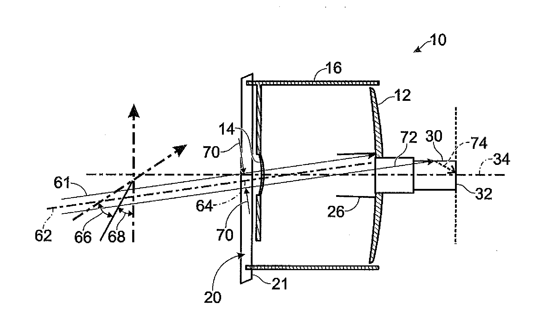
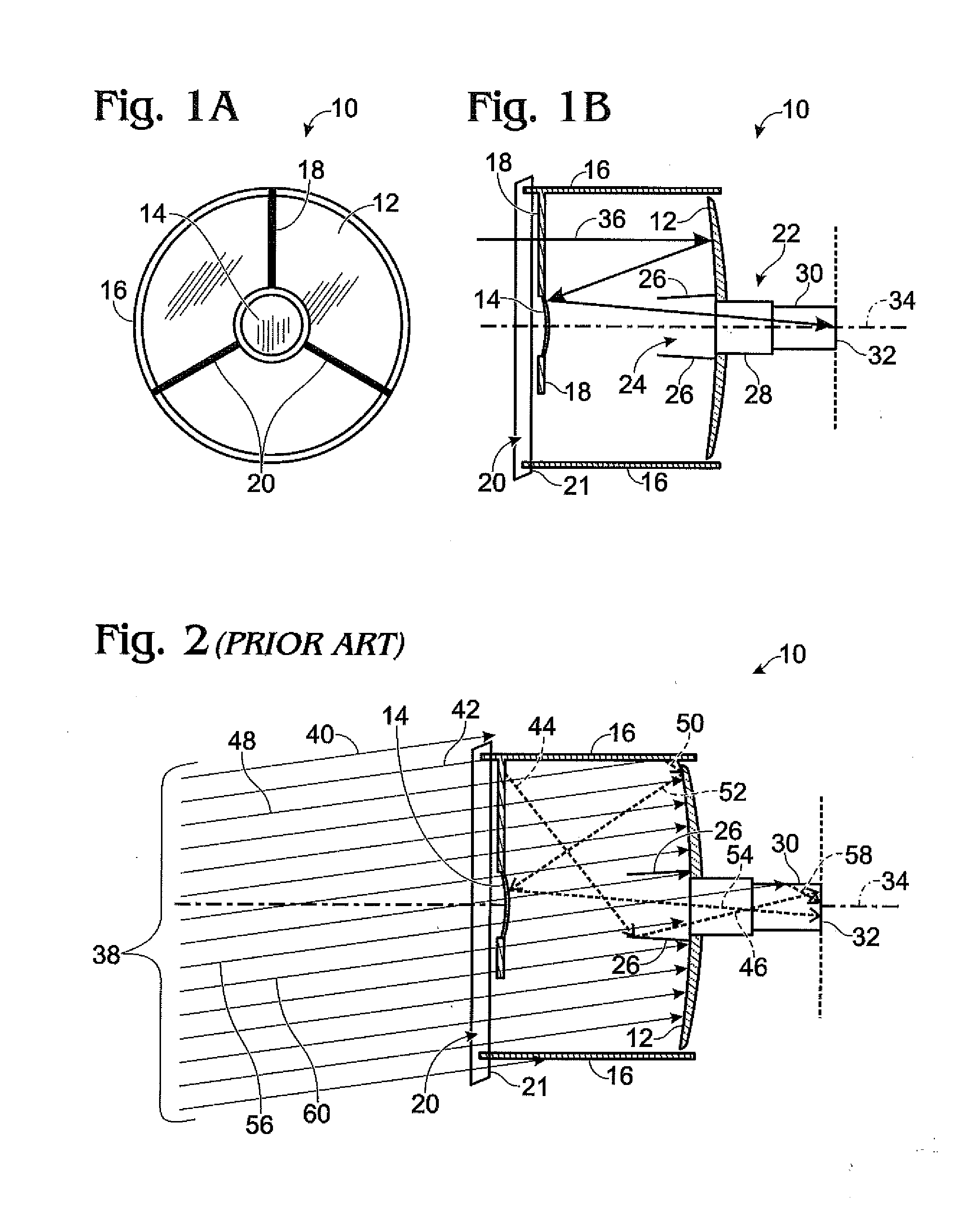
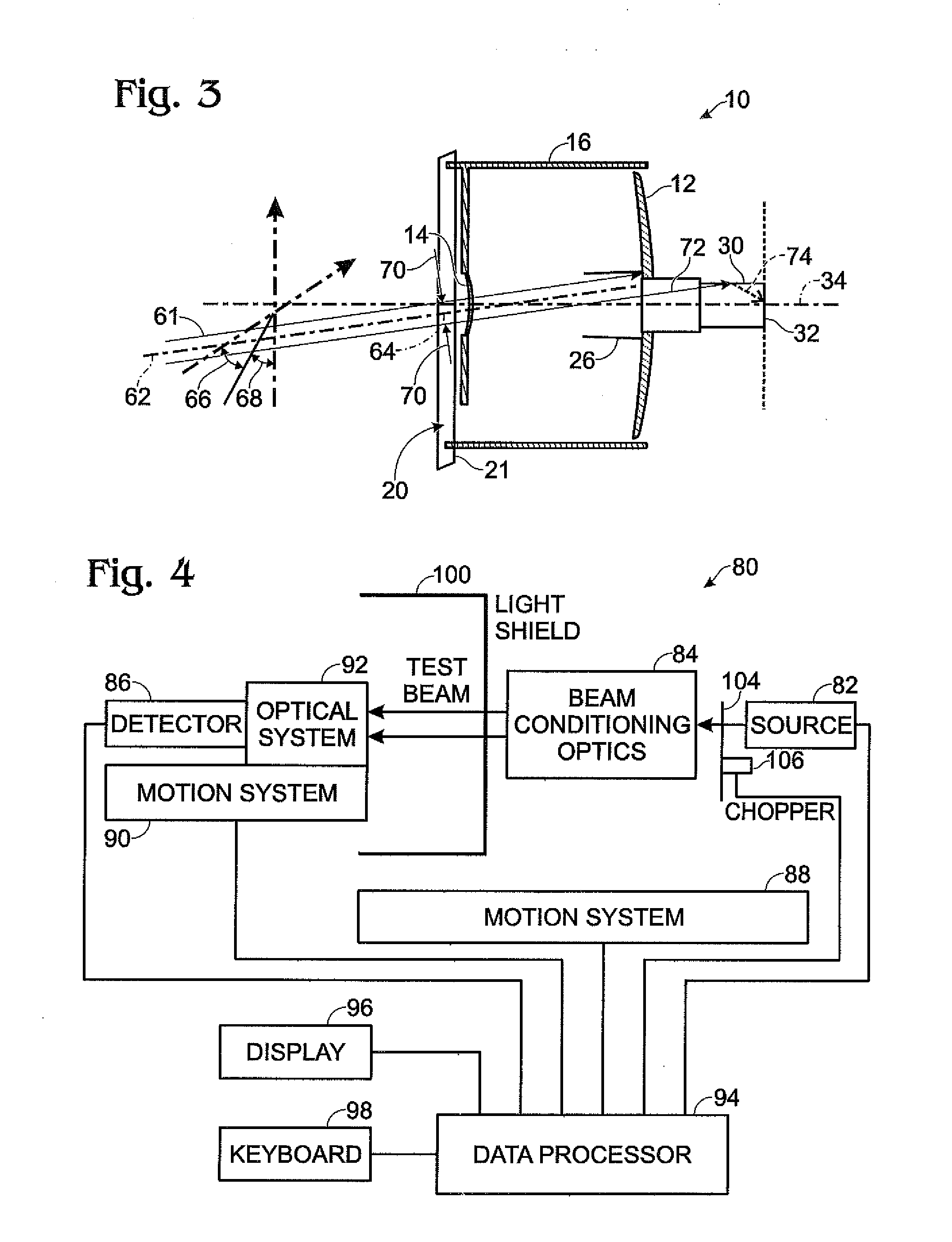
[0031]Referring first to FIG. 1A and FIG. 1B, an illustrative Cassegrain telescope 10 is shown as a vehicle for explaining the operation of embodiments of the invention herein. FIG. 1A is a front view of the Cassegrain telescope and FIG. 1B is a side-view of the Cassegrain telescope. The telescope comprises a primary mirror 12 and secondary mirror 14, a cylindrical baffle 16 in which the primary and secondary mirrors are disposed, struts 18 for suspending the secondary mirror 14 in the center of an entrance aperture 20 (the plane of which is symbolized by parallelogram 21), a detector assembly 22 disposed behind a detector aperture 24 in the primary mirror 12, and a Frustrum-shaped interior baffle 26 surrounding the detector aperture 24. The detector assembly 22 typically comprises a tubular third baffle 28 for accommodating the focal length of the telescope, a detector baffle 30, preferably having anti-reflective coating on the interior wall thereof, and an array detector 32 at the...


PUM


Abstract

A device and method for subaperture stray light detection and diagnosis in an optical system. A test light beam is generated with a width whose cross sectional area is less than the cross sectional area of a system aperture. Stray light is detected at a system detection surface. Based on the stray light and the location and direction angles of the light beam, potential paths that light may have taken to arrive at the detection surface are determined so as to identify physical features of the optical system that may have produced the stray light. A testing device comprises a test light beam source, preferably including a beam width magnifier, whereby the cross sectional area of the test light beam is made less than the cross sectional area of the system aperture. A relative lateral positioning stage and an angular beam directing stage launch the test light beam into the aperture at a selected position and selected directional angles. A detector and a data processing system produce a data set relating the stray light to the location and directional angles of the test light beam. A light trap and complementary test light beam delivery system are also provided.

Description

RELATED APPLICATIONS[0001]This application is a continuation-in-part of, and claims the benefit of priority of, U.S. patent application Ser. No. 12 / 836,457, filed Jul. 14, 2010, which is based on and claims the benefit of priority of U.S. Provisional Application No. 61 / 271,034, filed Jul. 16, 2009, both of which applications are hereby incorporated by reference in their entirety.FEDERALLY SPONSORED RESEARCH AND DEVELOPMENT[0002]Subject matter disclosed herein was developed under a contract with and agency of the United States Government, namely, the Missile Defense Agency, Contract No. HQ0006-09-C-7126. The Government has certain rights in this invention.BACKGROUND OF THE INVENTION[0003]1. Field of the Invention[0004]This invention relates in general to the field of stray-light detection and diagnosis in optical systems and, in particular, to a novel device and method for stray-light detection and diagnosis by illumination of the aperture of an optical system with a subaperture ligh...

Claims


Application Information

Patent Timeline
Patent Type & Authority Applications(United States)
IPC IPC(8): G01B11/26
CPCG01B11/26G01J1/0437G01J1/0214G01J1/0266G01J1/0228G01J1/0411G01J1/00
Inventor KUHN, WILLIAM P.STOVER, JOHN C.LECOMPTE, ROBERT S.
Owner WILLIAM P KUHN PH D
Learn More