Method and Apparatus of Transceiver Calibration Using Substrate Coupling

a technology of substrate coupling and transceiver, which is applied in the direction of electrical apparatus, digital transmission, transmission, etc., can solve the problems achieve the effects of reducing the sensitivity of the receiver, minimizing this coupling or loopback coupling, and improving the performance of the transceiver

Active Publication Date: 2013-10-10
TENSORCOM
View PDF1 Cites 32 Cited by
  • Summary
  • Abstract
  • Description
  • Claims
  • Application Information

AI Technical Summary

Benefits of technology

[0010]The RF transmit and RF receive chains can couple with one another via switching noise generated by each chain when the transceiver is in operation, particularly when the transceiver is on a common substrate. That is, signals are coupled between the RF transmit and RF receive chains via the substrate reactances, substrate impedances and surface metal reactances into the other chain. Each reactance can also have associated resistances. Multiple coupling paths can be formed between these two c...

Problems solved by technology

Multiple coupling paths can be formed between these two chains and is typically an undesirable ...

Method used


Image

  • Method and Apparatus of Transceiver Calibration Using Substrate Coupling
  • Method and Apparatus of Transceiver Calibration Using Substrate Coupling
  • Method and Apparatus of Transceiver Calibration Using Substrate Coupling

Examples


Embodiment Construction

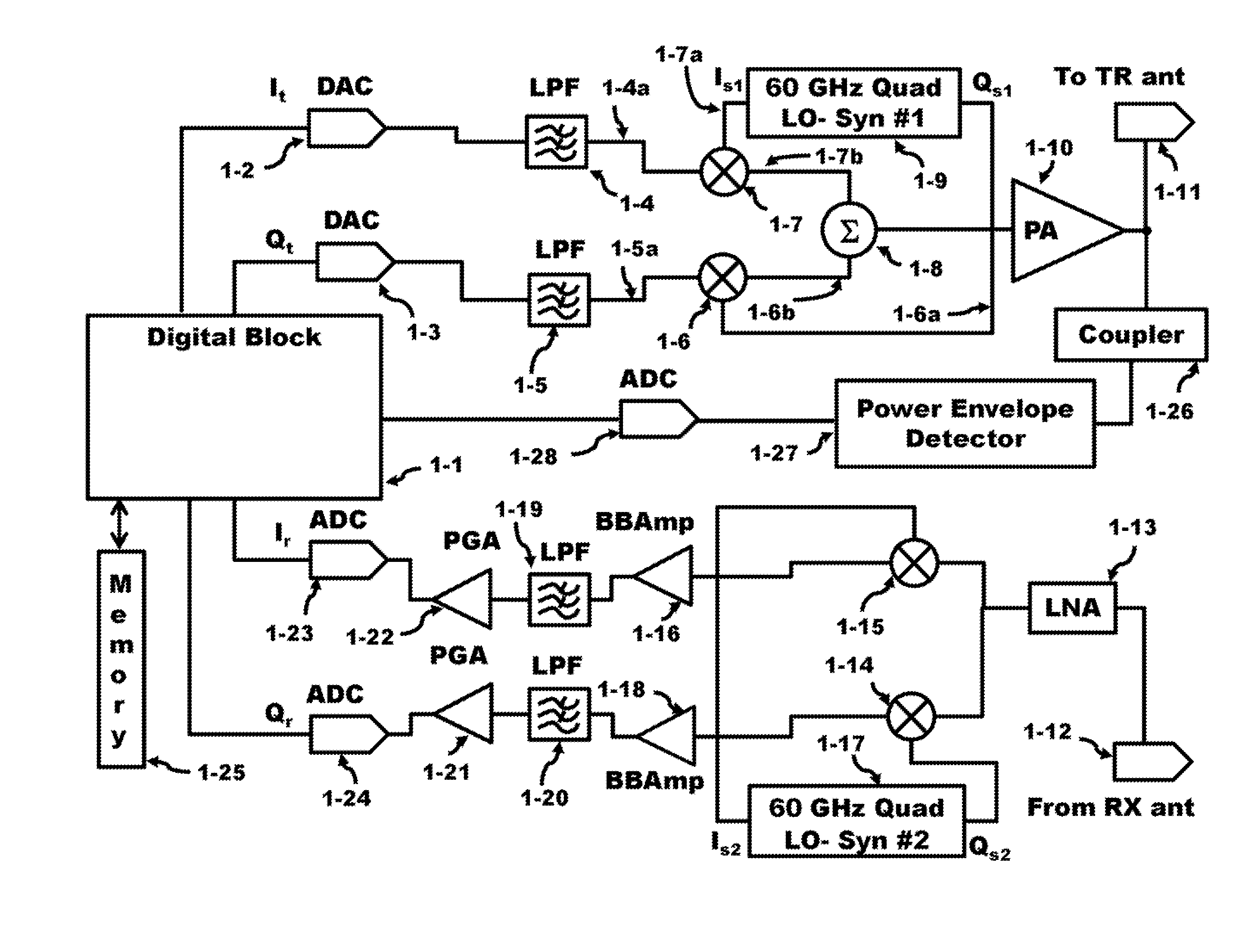
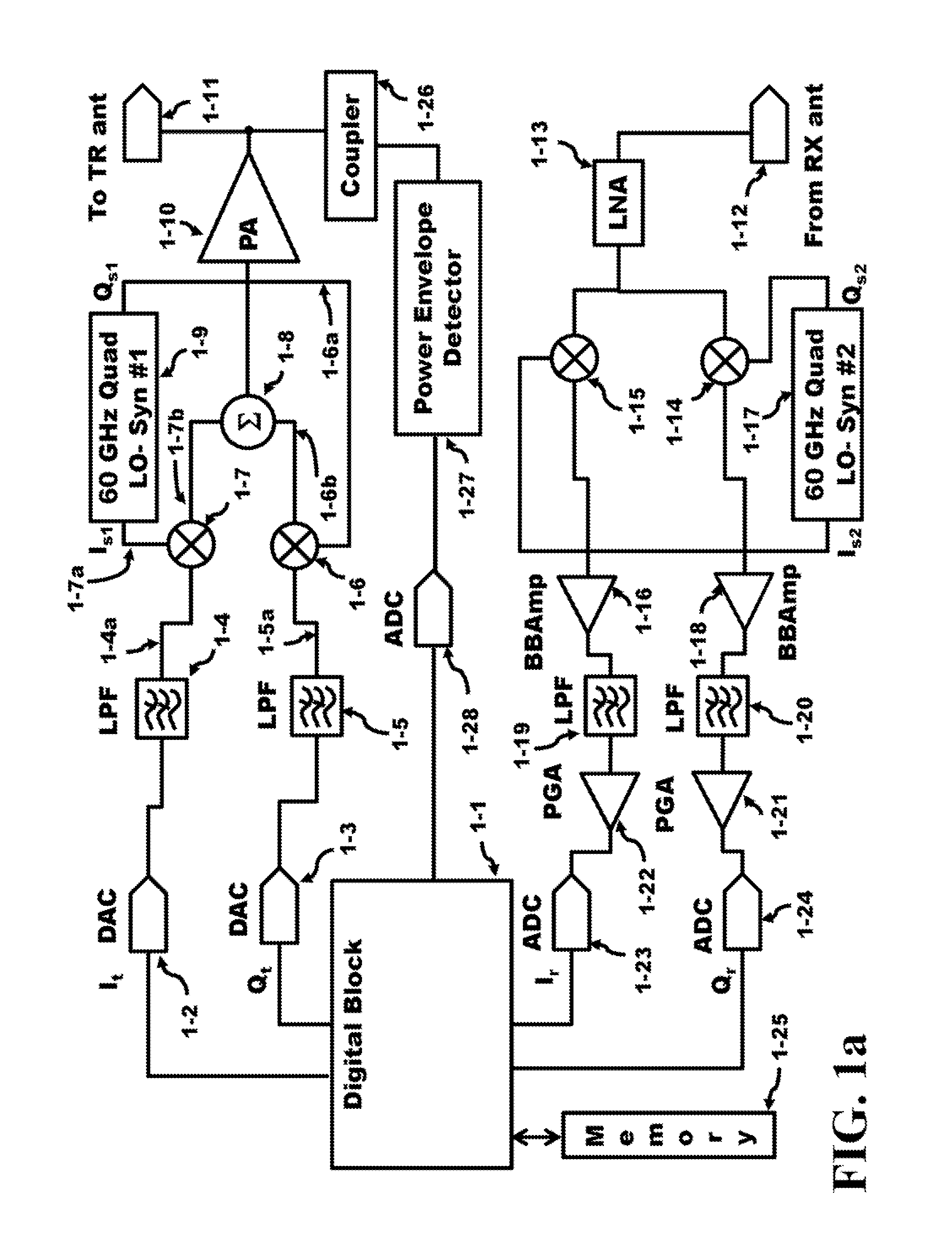
[0044]FIG. 1a illustrates a transceiver coupled to a digital block and provides I / Q signals for the RF transmit chain which couples to the transmit antenna 1-11. Starting from the digital block 1-1, the It digital signal is applied to the DAC 1-2 input while the Qt digital signal is applied to the input of DAC 1-3. The I and Q signals after the DAC are analog at this point and, ideally, represent differential signals that are 90° out of phase or orthogonal to each other where the amplitude of both signals are equal. These I and Q signals are then low pass filtered by the LPF 1-4 and LPF 1-5, respectively, to a bandwidth of about 900 MHz. In addition, all single lines coupling (or interconnecting) signals between analog blocks are in fact differential lines, unless noted otherwise. These differential lines are illustrated as a single line to simplify the diagram and when the single line is shown, it is understood that the line and the signal it carries represents a differential signa...


PUM


Abstract

Transceiver calibration is a critical issue for proper transceiver operation. The transceiver comprises at least one RF transmit chain and one RF receive chain. A closed loop path is formed from the digital block, the RF transmit chain, the substrate coupling, the RF receive chain back to the digital block and is used to estimate and calibrate the transceiver parameters over the operating range of frequencies. The substrate coupling eliminates the need for the additional circuitry saving area, power, and performance. In place of the additional circuitry, the digital block which performs baseband operations can be reconfigured into a software or/and hardware mode to calibrate the transceiver. The digital block comprises a processor and memory and is coupled to the front end of the RF transmit chain and the tail end of the RF receive chain.

Description

CROSS REFERENCE TO RELATED APPLICATIONS[0001]U.S. patent application Ser. No. 13 / 243,880, filed Sep. 23, 2011 by Zaw Soe under the title, “Differential Source Follower having 6 dB Gain with Applications to WiGig Baseband Filters”; U.S. patent application Ser. No. 13 / 243,986, filed Sep. 23, 2011 by Zaw Soe under the title, “Method and Apparatus of Minimizing Extrinsic Parasitic Resistance in 60 GHz Power Amplifier Circuits”; and U.S. patent application Ser. No. 13 / 312,806, filed Dec. 6, 2011 by Zaw Soe under the title, “Method and Apparatus of an Input Resistance of a Passive Mixer to Broaden the Input Matching Bandwidth of a Common Source / Gate LNA” all commonly assigned herewith, disclose certain subject matter which is common hereto.BACKGROUND OF THE INVENTION[0002]The Federal Communications Commission (FCC) has allotted a spectrum of bandwidth in the 60 GHz frequency range (57 to 64 GHz). The Wireless Gigabit Alliance (WiGig) is targeting the standardization of this frequency band...

Claims


Application Information

Patent Timeline
IPC IPC(8): H04B1/38
CPCH04B1/30H04B1/123H04B1/525
Inventor LAKKIS, ISMAIL
Owner TENSORCOM
Why Eureka
Try Eureka