
Rare earth sintered magnet and making method

a making method technology, applied in the field of high-performance rare earth sintered magnets, can solve the problems of unavoidable trade-off between coercivity and remanence, decline of remanence (or residual magnetic flux density), and only about 15% (1 ma/m) of anisotropic magnetic field coercive force actually available, and achieve excellent magnetic properties and high coercivity.

Inactive Publication Date: 2013-10-17
SHIN ETSU CHEM IND CO LTD
View PDF3 Cites 32 Cited by
  • Summary
  • Abstract
  • Description
  • Claims
  • Application Information

AI Technical Summary

Benefits of technology

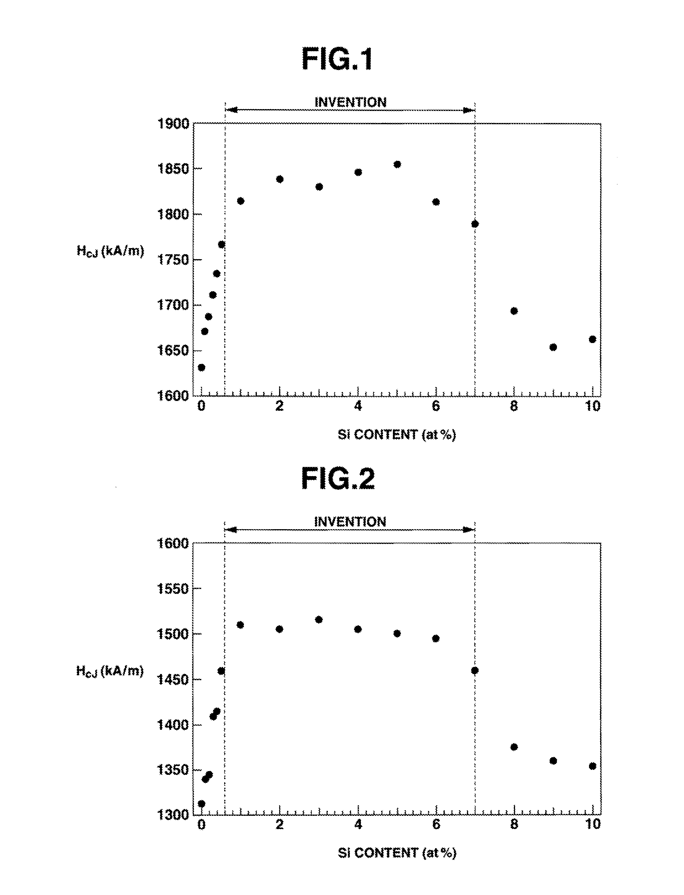
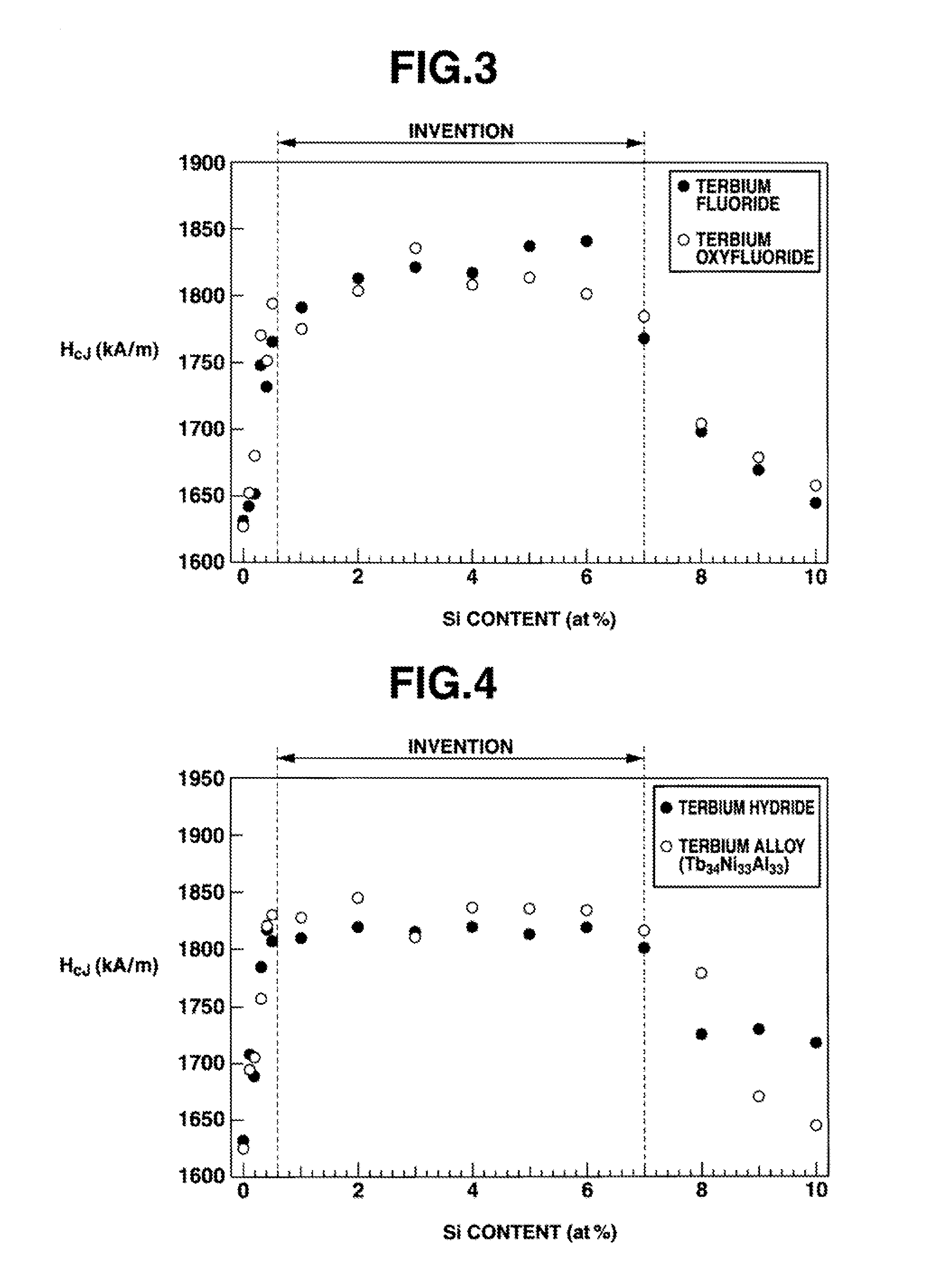
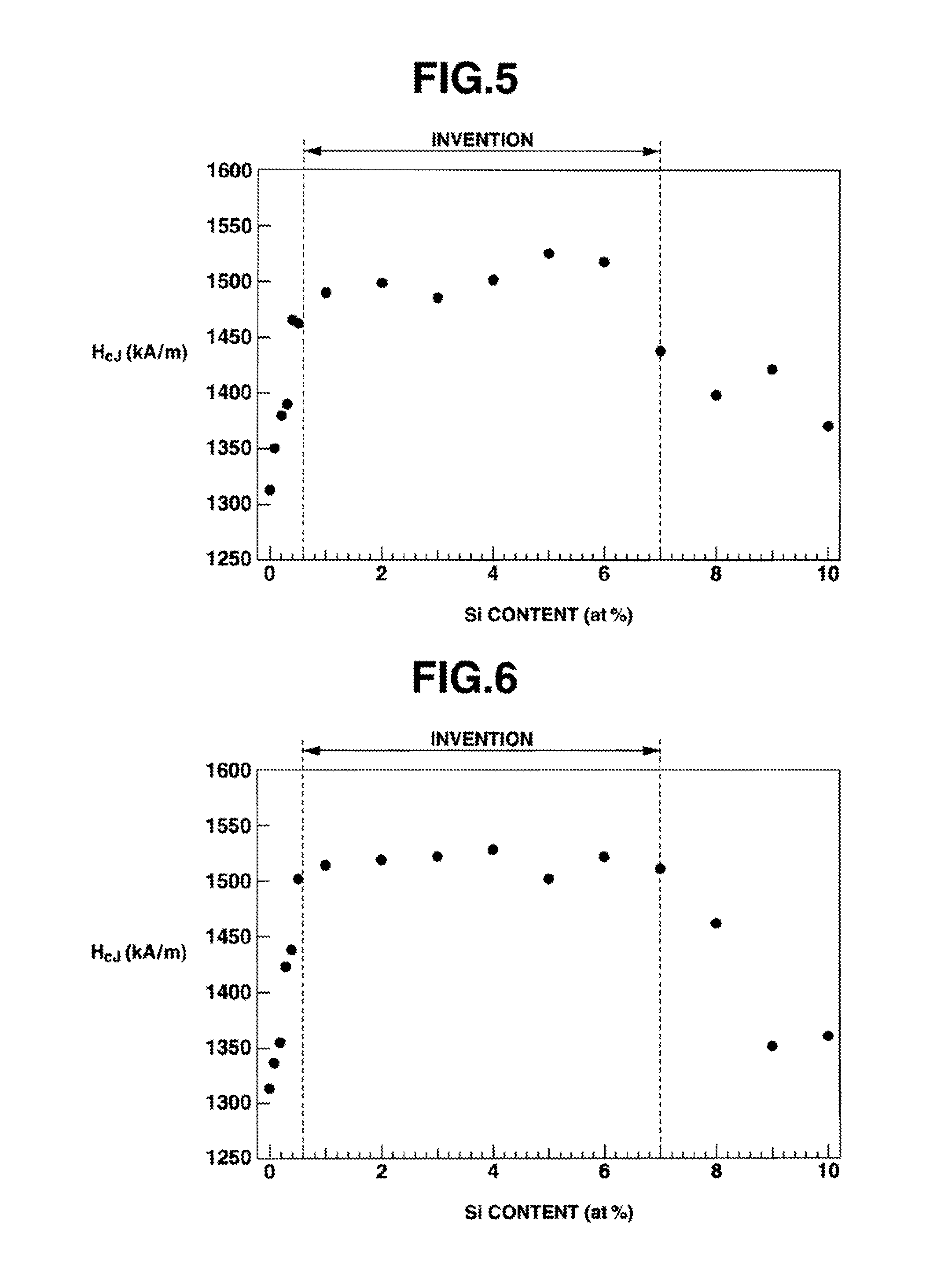
The rare earth sintered magnet is made from an anisotropic sintered body with silicon that allows rare earth elements (Dy and / or Tb) to easily move along grain boundaries. This results in a high coercivity and excellent magnetic properties, even at low content levels of rare earth elements.

Problems solved by technology

However, because of a reduction of the anisotropic magnetic field caused by disorder of the crystal structure near grain boundaries and the influence of leakage magnetic field caused by morphology or the like, the coercive force actually available is only about 15% (1 MA / m) of the anisotropic magnetic field.
However, since Dy and Tb cause a significant loss of saturation magnetization polarization of magnetic compounds, an attempt to increase the coercive force by addition of these elements is inevitably followed by a decline of remanence (or residual magnetic flux density).
That is, a tradeoff between coercivity and remanence is unavoidable.
The coating step is thus a time and labor-consuming operation including the time taken until the predetermined thickness is reached.
It is difficult to charge the heat treatment furnace with the number of magnet pieces compliant with its capacity, resulting in low productivity.

Method used


Image

  • Rare earth sintered magnet and making method
  • Rare earth sintered magnet and making method
  • Rare earth sintered magnet and making method

Examples


example 12

[0097]Three ribbon form alloys consisting of 14.5 at % Nd, 0.2 at % Cu, 6.2 at % B, 1.2 at % Al and 1.2 at % Si, 2 at % Al and 3 at % Si, or 5 at % Al and 3 at % Si, and the balance of Fe were prepared by the strip casting technique, specifically by using Nd, Al, Fe and Cu metals having a purity of at least 99 wt %, Si having a purity of 99.99 wt %, and ferroboron, high-frequency heating in an Ar atmosphere for melting, and casting the melt onto a single chill roll of copper. The alloys were exposed to 0.11 MPa of hydrogen at room temperature so that hydrogen was absorbed therein, heated up to 500° C. while vacuum pumping so that hydrogen was partially desorbed, cooled, and sieved, collecting a coarse powder under 50 mesh.

[0098]Each coarse powder was finely pulverized on a jet mill using high pressure nitrogen gas, into a fine powder having a median diameter of 50 μm. The fine powder was compacted under a pressure of about 1 ton / cm2 in a nitrogen atmosphere while being oriented in a...

example 13

[0102]Magnet blocks were prepared as in Example 12 except that dysprosium oxide (average particle size 0.35 μm, average coating weight 50±5 μg / mm2) was used instead of terbium oxide.

[0103]The coercivity of the resulting magnet blocks was measured, with the results shown below.

Magnet with Al and Si contentsCoercivity1.2 at % Al and 1.2 at % Si1,701 kA / m3 at % Al and 2 at % Si1,758 kA / m5 at % Al and 3 at % Si1,863 kA / m


PUM

PropertyMeasurementUnit
temperatureaaaaaaaaaa
sizeaaaaaaaaaa

Abstract

A rare earth sintered magnet as an anisotropic sintered body comprising Nd2Fe14B crystal phase as primary phase and having the composition R1aTbMcSidBe wherein R1 is a rare earth element inclusive of Sc and Y, T is Fe and / or Co, H is Al, Cu, Zn, In, P, S, Ti, V, Cr, Mn, Ni, Ga, Ge, Zr, Nb, Mo, Pd, Ag, Cd, Sn, Sb, Hf, Ta, or W, “a” to “e” are 12≦a≦17, 0≦c≦10, 0.3≦d≦7, 5≦e≦10, and the balance of b, wherein Dy and / or Tb is diffused into the sintered body from its surface.

Description

CROSS-REFERENCE TO RELATED APPLICATION[0001]This non-provisional application claims priority under 35 U.S.C. 119(a) on Patent Application Nos. 2012-090070, 2012-090078 and 2012-090099 filed in Japan on Apr. 11, 2012, Apr. 11, 2012 and Apr. 11, 2012, respectively, the entire contents of which are hereby incorporated by reference.TECHNICAL FIELD[0002]This invention relates to high-performance rare earth sintered magnets with minimal contents of expensive Tb and Dy, and a method for preparing the same.BACKGROUND ART[0003]Over the years, Nd—Fe—B sintered magnets find an ever increasing range of application including hard disk drives, air conditioners, industrial motors, power generators and drive motors in hybrid cars and electric vehicles. When used in air conditioner compressor motors, vehicle-related components and other applications which are expected of future development, the magnets are exposed to elevated temperatures. Thus the magnets must have stable properties at elevated tem...

Claims


Application Information

Patent Timeline
Patent Type & Authority Applications(United States)
IPC IPC(8): H01F1/03H01F41/00
CPCH01F1/0311H01F41/005B22F2003/248C21D6/004C21D6/005C21D6/007C21D6/008C22C28/00C22C33/02C22C38/002C22C38/005C22C38/007C22C38/008C22C38/02C22C38/04C22C38/06C22C38/105C22C38/12C22C38/14C22C38/16C22C38/20C22C38/60C22C2202/02H01F1/0577H01F41/0293H01F1/058B22F3/1017B22F3/26B22F2301/35B22F2998/10H01F1/0536H01F41/0266
Inventor NAGATA, HIROAKIGOUKI, YUUJISAKAKI, KAZUAKINOMURA, TADAOHIROTA, KOICHINAKAMURA, HAJIME
Owner SHIN ETSU CHEM IND CO LTD
Learn More