
Blow Molded Thermoplastic Composition

a technology of thermoplastic composition and blow molding, which is applied in the direction of synthetic resin layered products, packaging, propulsion parts, etc., can solve the problems of phase separation, incompatibility of elastomeric polymers generally considered useful for impact modification, and use of blow molding components, etc., to achieve excellent material characteristics

Active Publication Date: 2013-10-17
TICONA LLC
View PDF3 Cites 24 Cited by
  • Summary
  • Abstract
  • Description
  • Claims
  • Application Information

AI Technical Summary

Benefits of technology

The patent text describes a component made from a blow molded thermoplastic composition that includes a polyarylene sulfide and a crosslinked impact modifier. This composition has excellent material characteristics, including a high notched Charpy impact strength and a low tensile modulus. The method includes blow molding the thermoplastic composition and the components can be used in harsh environments such as in transportation applications or oil and gas field components. Examples include fuel system components, interior and exterior components, and engine components.

Problems solved by technology

Many of the applications that could benefit from the utilization of blow molded components are quite demanding, and require components that can withstand a variety of both chemical and mechanical insults.
Unfortunately, elastomeric polymers generally considered useful for impact modification are not compatible with polyarylene sulfides and phase separation has been a problem in forming compositions of the two.
However, even upon such modifications, compositions including polyarylene sulfides in combination with impact modifying polymers still fail to provide product performance as desired, particularly in applications that require both high heat resistance and high impact resistance.

Method used


Image

  • Blow Molded Thermoplastic Composition
  • Blow Molded Thermoplastic Composition
  • Blow Molded Thermoplastic Composition

Examples


example 1

[0186]Materials utilized to form the compositions included the following:

[0187]Polyarylene sulfide: Fortron® 0214 linear polyphenylene sulfide available from Ticona Engineering Polymers of Florence, Ky.

[0188]Impact Modifier: LOTADER® AX8840—a random copolymer of ethylene and glycidyl methacrylate available from Arkema, Inc.

[0189]Crosslinking Agent: Terephthalic Acid

[0190]Disulfide: 2,2-dithiodibenzoic acid

[0191]Lubricant: Glycolube® P available from Lonza Group Ltd.

[0192]Materials were melt mixed using a Coperion co-rotating, fully-intermeshing, twin-screw extruder with an overall L / D of 40 and ten temperature control zones including one at the die. A high shear screw design was used to compound the additives into a resin matrix. The polyarylene sulfide, impact modifier and lubricant were fed to the main feed throat in the first barrel by means of a gravimetric feeder. Upon melting and mixing of the above ingredients, the disulfide was fed using a gravimetric feeder at barrel 6. Mat...

example 2

[0197]Materials as described in Example 1 were melt mixed using a Coperion co-rotating, fully-intermeshing, twin-screw extruder with an overall L / D of 40 and ten temperature control zones including one at the die. A high shear screw design was used to compound the additives into a resin matrix. The polyarylene sulfide, impact modifier and lubricant were fed to the main feed throat in the first barrel by means of a gravimetric feeder. The disulfide was fed using a gravimetric feeder at various locations in the extruder; at the main feed throat, at barrel 4 and barrel 6. The crosslinking agent was fed at barrel 6. Materials were further mixed then extruded through a strand die. The strands were water-quenched in a bath to solidify and granulated in a pelletizer.

[0198]Comparative Samples 3 and 4 were formed of the same composition and compounded by use of a different screw design.

TABLE 4AdditionPoint345678910Lubricantmain feed0.30.30.30.30.30.30.30.3Crosslinking Agentbarrel 6——0.51.01....

example 3

[0206]Materials as described in Example 1 were melt mixed using a Coperion co-rotating, fully-intermeshing, twin-screw extruder with an overall L / D of 40 and ten temperature control zones including one at the die. A high shear screw design was used to compound the additives into a resin matrix. The polyarylene sulfide, impact modifier and lubricant were fed to the feed throat in the first barrel by means of a gravimetric feeder. The crosslinking agent was fed using a gravimetric feeder at the main feed throat and at barrel 6. Materials were further mixed then extruded through a strand die. The strands were water-quenched in a bath to solidify and granulated in a pelletizer.

[0207]Compositions of the samples are provided in Table 8, below. Amounts are provided as weight percentages based upon the weight of the sample.

TABLE 8AdditionSampleSampleSampleSampleComponentPoint11121314Lubricantmain0.30.30.30.3feedCrosslinkingmain—0.51.0—AgentfeedCrosslinkingbarrel 6———1.0AgentImpactmain15.015...


PUM

PropertyMeasurementUnit
temperatureaaaaaaaaaa
notched Charpy impact strengthaaaaaaaaaa
elongation at yieldaaaaaaaaaa

Abstract

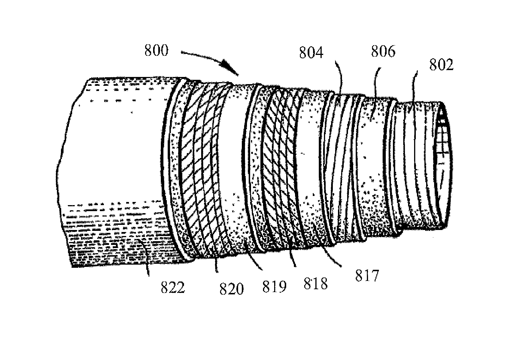
Components formed of blow molded thermoplastic compositions are described. The blow molded thermoplastic compositions exhibit high strength and flexibility. Methods for forming the thermoplastic compositions are also described. Formation methods include dynamic vulcanization of a composition that includes an impact modifier dispersed throughout a polyarylene sulfide. A crosslinking agent is combined with the other components of the composition following dispersal of the impact modifier. The crosslinking agent reacts with the impact modifier to form crosslinks within and among the polymer chains of the impact modifier. The compositions can exhibit excellent physical characteristics at extreme temperatures and can be used to form, e.g., tubular member such as pipes and hoses and fibers.

Description

CROSS REFERENCE TO RELATED APPLICATIONS[0001]The present application claims filing benefit of U.S. Provisional Patent Application Ser. No. 61 / 623,618 having a filing date of Apr. 13, 2012, U.S. Provisional Patent Application Ser. No. 61 / 665,423 having a filing date of Jun. 28, 2012, U.S. Provisional Patent Application Ser. No. 61 / 678,370 having a filing date of Aug. 1, 2012, U.S. Provisional Patent Application Ser. No. 61 / 703,331 having a filing date of Sep. 20, 2012, U.S. Provisional Patent Application Ser. No. 61 / 707,320 having a filing date of Sep. 28, 2012, and U.S. Provisional Patent Application Ser. No. 61 / 717,946 having a filing date of Oct. 24, 2012, all of which are incorporated herein in their entirety by reference.BACKGROUND OF THE INVENTION[0002]Blow molding has been utilized for a number of years to form a variety of hollow plastic parts. It has proven effective to form single layer as well as multi-layer materials and, with more recent advances, has been used to form a...

Claims


Application Information

Patent Timeline
Patent Type & Authority Applications(United States)
IPC IPC(8): C08L63/00B60K15/03B32B1/08C08L81/04
CPCC08L63/00C08L81/04B60K15/03177B32B1/08C08L33/068C08L81/02Y10T428/1352Y10T428/139Y10T428/1393B32B27/286B32B2307/3065B32B2307/54B32B2307/546B32B2307/558B32B2307/7242B32B2307/7265B32B2439/40B32B2597/00B32B2605/08B60K15/04B60K2015/03039B60K2015/0458C08L2205/06C08L2207/04
Inventor LUO, RONGZHAO, XINYUGRENCI, JOSEPH
Owner TICONA LLC
Learn More