Digital closed-loop fiber optical current sensor

a digital technology, applied in the direction of resistance/reactance/impedence, voltage-current phase angle, instruments, etc., can solve the problems of reducing the measurement precision in the tiny signal range, slow response speed, and none of the problems of precision and long-term stability, so as to improve the bandwidth, sensitivity and dynamic range of the digital closed-loop fiber optical current sensor. , the effect of reducing the noise power level of the digital closed-l

Inactive Publication Date: 2013-10-24
CHINA ELECTRIC POWER RES INST
View PDF1 Cites 10 Cited by
  • Summary
  • Abstract
  • Description
  • Claims
  • Application Information

AI Technical Summary

Benefits of technology

[0020]The main objective of this present invention is: to reduce the noise power level of the digital closed-loop fiber optical cu

Problems solved by technology

However, the signal processing circuit of this fiber optical current sensor accepts optical loss passively only, and can't interference its work (1980, several polarimeter closed-loop fiber optical current sensor were proposed, but they all were abandoned owing to slow response speed and large power consumption in principle, see literature [1, see IDS]).
None of them can solve precision and long-term stability problem due to environment temperature, vibration induced birefringence.
But there are some problems of this kind of fiber optical current sensor, that polarization model of optical fiber current s

Method used


Image

  • Digital closed-loop fiber optical current sensor
  • Digital closed-loop fiber optical current sensor
  • Digital closed-loop fiber optical current sensor

Examples


Embodiment Construction

[0053]The detail of the embodiments is described as below incorporated with the figures by way of cross-reference.

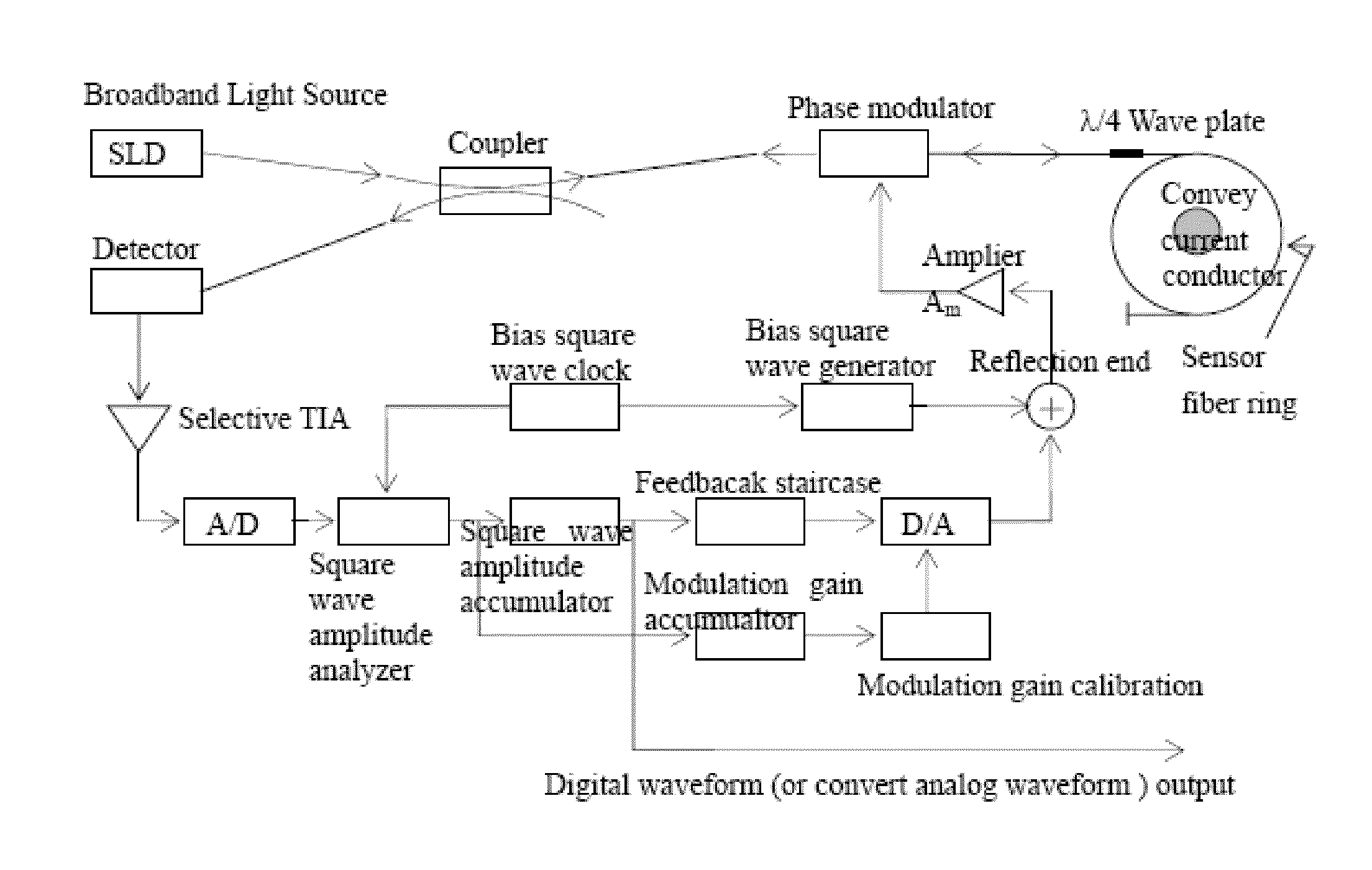
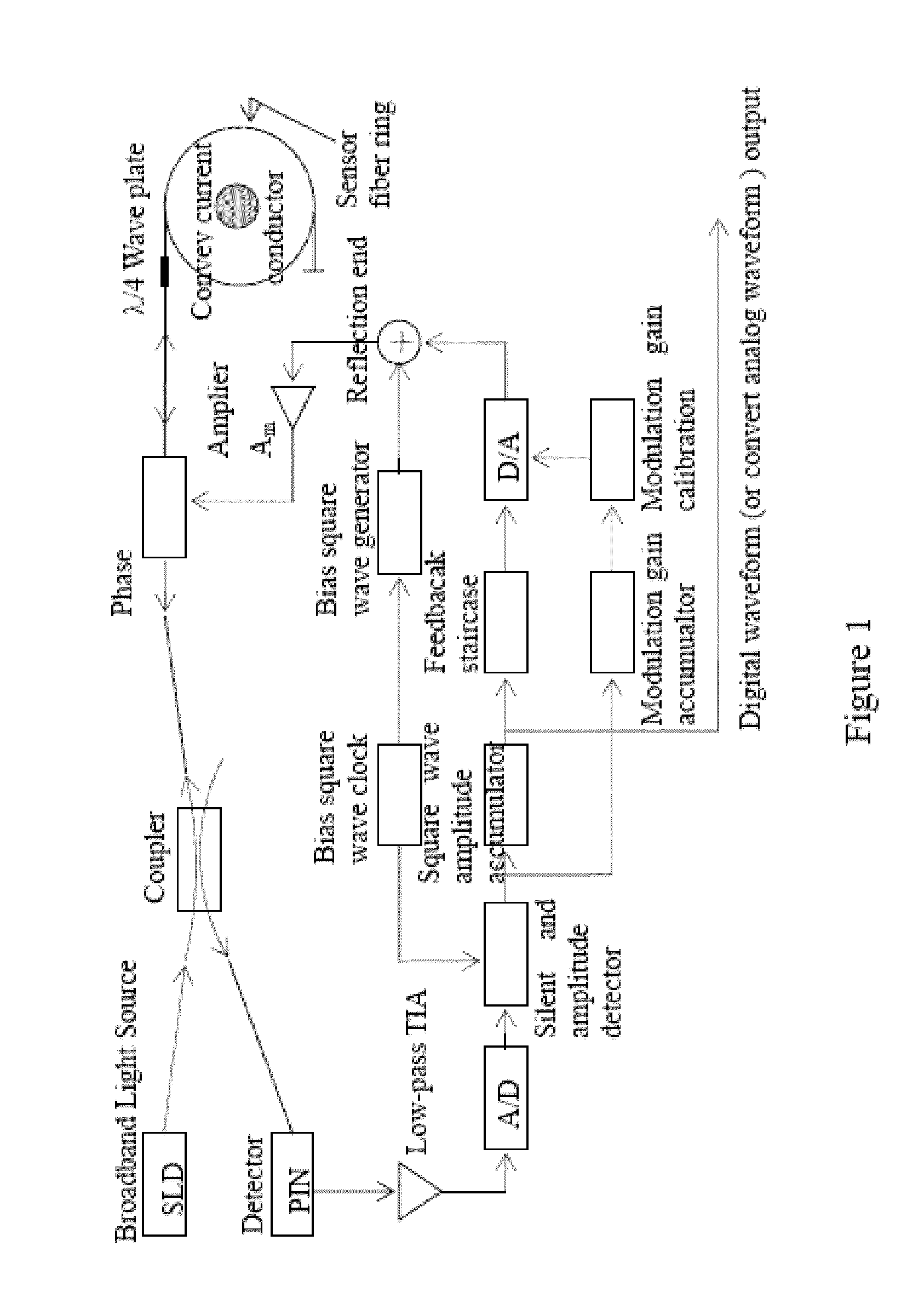
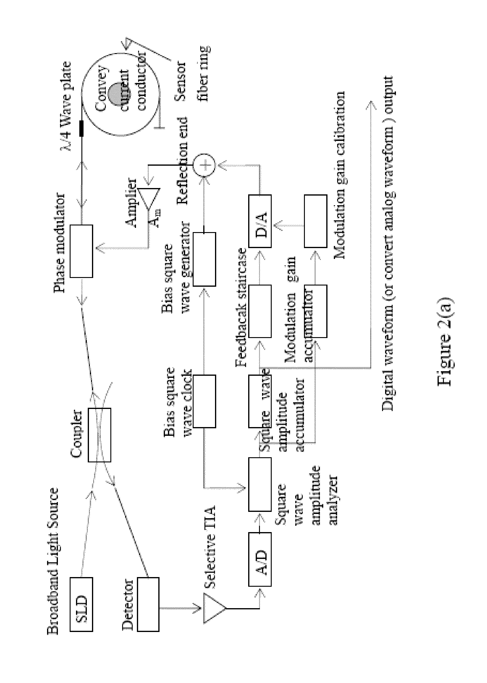
[0054]In order to improve the dynamic range and the response speed of the digital closed-loop fiber optical current sensor, the noise power level of the preamplifier output signal of the signal processing system can be reduced. It not only increases the measurement accuracy in the tiny signal range, but also deceases the lag time of signal process. The solution of the present invention provided is described as below: wave phase modulation adopted square wave, signal processing did not us square wave but based on the sine wave (Hereafter referred to as the square wave—sine wave scheme). In order to explain why this design can achieve the goal, the application first analyze the characteristics of the signals need to process of the digital closed-loop fiber optical current sensor.

[0055]As a example, the FIG. 1 is the simplified circuit and optical path diagram of the existi...


PUM


Abstract

This present inversion provides a digital closed-loop fiber optical current sensor. The modulation signal of the optical wave “phase modulator” of the fiber optical current sensor system is modulation square wave, signal processing system extracts any harmonic wave of the photoelectric converter output modulation square waves, and extracts the measured current information from it. The preamplifier of signal processing system is transimpedance amplifier TIA, the bandwidth is extracted 1/650 instantaneous amplitude square wave directly from the modulation square wave (existing), thus the thermal noise of the preamplifier output and shot noise level is reduced to the existing technology of below 1/650; the current-voltage gain of transimpedance amplifier TIA does not depend on the feedback network resistance, thus it can have high current-voltage conversion gain and use low resistance in the feedback network TIA at the same time. So it can reduce resistance thermal noise to negligible that is accounted for a large proportion of TIA output noise.

Description

TECHNICAL FIELD[0001]The present invention relates to sensitive electronics and sensor field in electronics information system, also to high voltage and high current field in electrotechnics, and particularly relates to a digital closed-loop fiber optical current sensor. The present invention also applies to digital closed fiber optical gyro, and various digital closed-loop fiber optic interferometers including digital closed-loop fiber optic Sagnac interferometer, and particularly sensor, gyro and interferometer that the output of extracted light signal is very weak.BACKGROUND OF INVENTION[0002]With the development of power system, the new techniques based on power electronics were more widely used in power system like DC transmission technology, flexible AC transmission technology, and digital substation technology and so on. In power system, the need is more urgent than ever before for practical optical current / voltage sensor (hereinafter referred to as fiber optical current sens...

Claims


Application Information

Patent Timeline
IPC IPC(8): G01R15/24
CPCG01R15/247
Inventor CHEN, XIANGXUNGUO, JIANBOJING, PINGCHEN, SHUOYIN, SHUJIELIU, ZHANYUAN
Owner CHINA ELECTRIC POWER RES INST
Why Eureka
Try Eureka