Coil assembly comprising planar coil

a coil and planar coil technology, applied in the direction of coils, electromagnets, inductances, etc., can solve problems such as device degradation, achieve the effects of reducing coil resistance and power loss, avoiding long deposition times of thicker magnetic films, and enhancing cooling

Inactive Publication Date: 2013-10-24
AAC CLYDE SPACE AB
View PDF4 Cites 30 Cited by
  • Summary
  • Abstract
  • Description
  • Claims
  • Application Information

AI Technical Summary

Benefits of technology

[0011]In a preferable embodiment of the invention, the height of the turns of the coil is in the range of more than 100 μm up to 1100 μm, or preferably in the range of more than 150 μm up to 1100 μm or even more preferably in the range of more than 200 μm up to 1100 μm. This provides the further advantages of reduced coil resistance and power losses as well as enhanced cooling under high current densities.
[0012]Another object of the invention is to provide a method to manufacture a coil assembly according to the invention. The method comprises providing a first magnetic core plate with at least one trench, formed as a flat helix, and at least one via hole. Subsequently, the material which forms the coil is deposited in the trench or trenches and the material which forms the tap or taps is deposited in the via hole or via holes, so that the coil and the at least one tap are integrally formed thus removing any need for an intermediate light etching or cleaning step and a second process step to deposit the material forming the at least one tap. Preferably, the material which forms a contact pad connected to the at least one tap is deposited in the same step as the coil and the at least one tap, so that the at least one tap is also integrally formed with a respective contact pad. The method does not require any deposition of magnetic core material, and thereby cracking, peeling, delamination and the long deposition times for thicker magnetic films are avoided. This method further provides the possibility to increase the height of the turns of the coil and reduce the spacing between the turns. This is possible since depositing the coil conducting material in a trench means that the cross-sectional shape of the turns of the coils is not limited by the risk of collapsing structures which may occur during lithography, etching and cleaning of a freestanding structure used in traditional fabrication methods.

Problems solved by technology

Any such interface could cause device degradation.

Method used


Image

  • Coil assembly comprising planar coil
  • Coil assembly comprising planar coil
  • Coil assembly comprising planar coil

Examples


Embodiment Construction

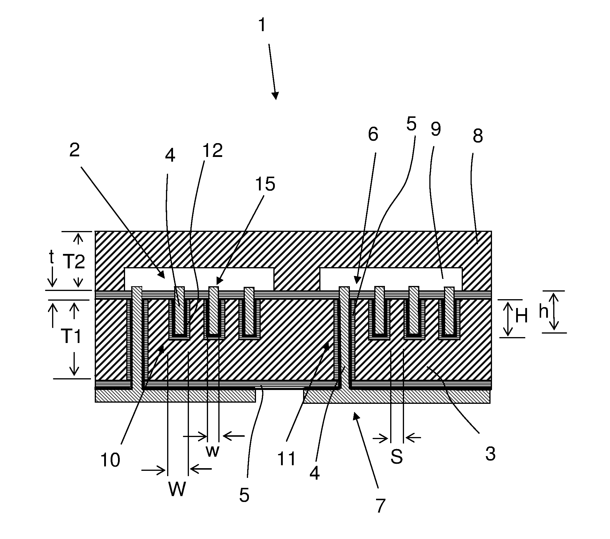
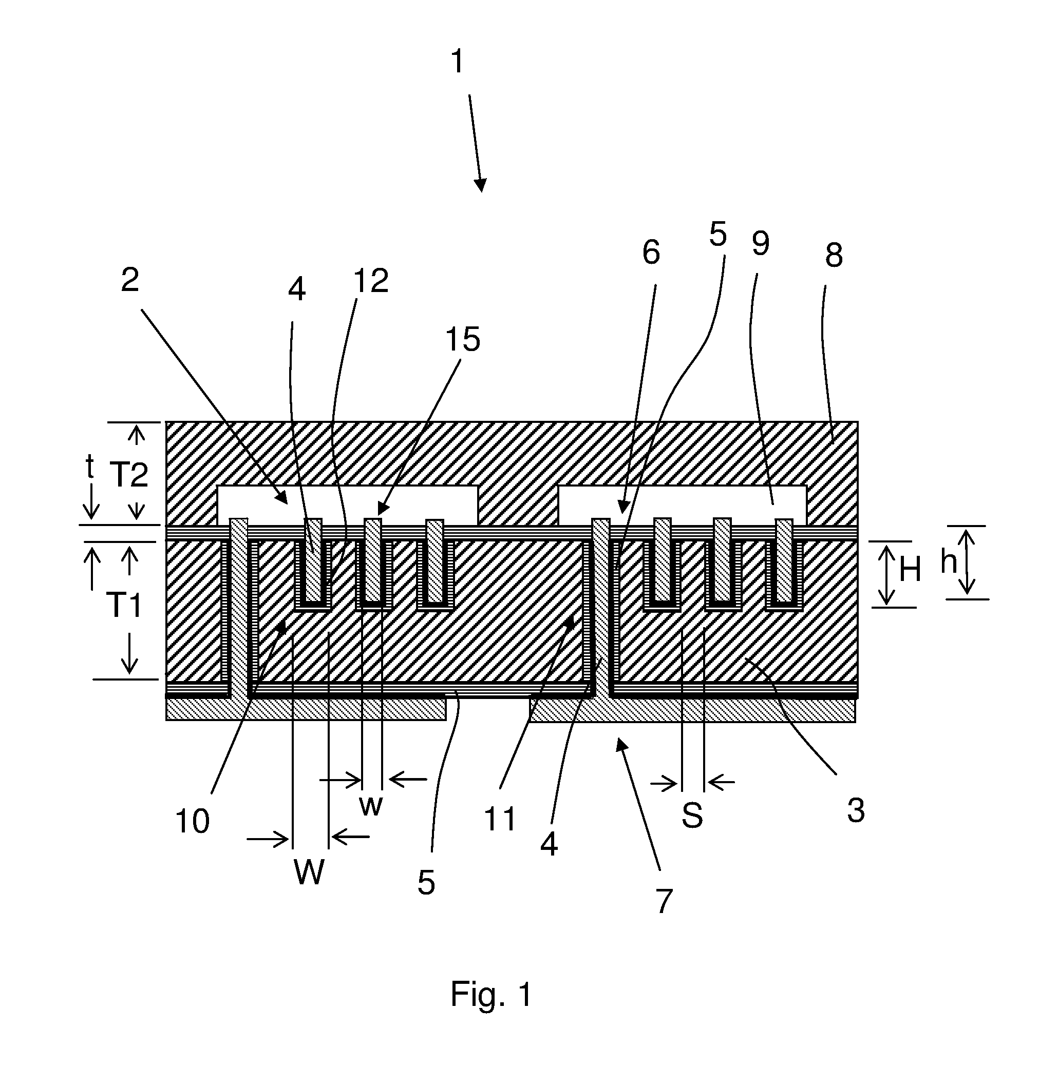
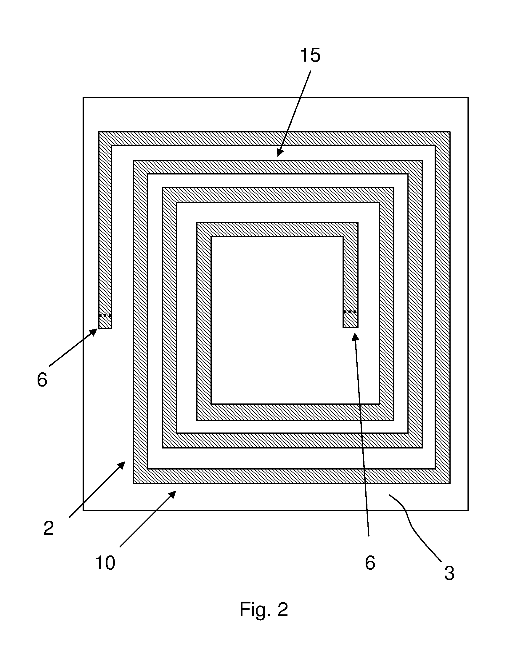
[0029]When the same reference number is included in several figures it denotes the same type of feature. FIG. 1 shows a lateral view of a coil assembly 1 according to the present invention comprising a planar coil 2, made of coil conducting material 4, preferably copper (Cu), for example Cu deposited on a seed layer 12 made of, for example, titanium (Ti) and copper (Cu), or titanium tungsten (TiW) and copper (Cu), comprising at least one turn 15 located in a trench 10 in a first magnetic core plate 3. The trench 10 is formed in the shape of the coil 2. The trench 10 preferably has a depth H in the range from 100 μm to 1000 μm. The width W of the turns 15 of the trench 10 is preferably in the range of 50 μm to 1000 μm, even more preferably in the range of 200 μm to 800 μm. Spacing S between two adjacent edges of two adjacent turns 15 of the trench 10 is preferably in the range of 50 μm to 1000 μm. The ratio of the width W of each turn 15 of the trench 10 to the depth H of the trench ...


PUM

PropertyMeasurementUnit
thicknessaaaaaaaaaa
heightaaaaaaaaaa
heightaaaaaaaaaa

Abstract

Coil assembly (1) comprising a planar coil (2) comprising a plurality of turns (15) arranged in a trench (10) in a first magnetic core plate (3) and a second magnetic core plate (8), where the first magnetic core plate (3) and second magnetic core plate (8) are in direct contact with each other or separated by an electrically insulating insulator layer (5) with a thickness (t) equal to or less than 50 μm and least one tap (6) extends from the coil (2) in a respective via hole (11) through the first magnetic core plate (3) to a respective contact pad (7), wherein the coil (2) and the tap (6) are integrally formed.

Description

TECHNICAL FIELD OF INVENTION[0001]The present invention relates to surface mountable coil assemblies, transformers with a planar coil or planar coils, and methods for making these.BACKGROUND OF THE INVENTION[0002]In many applications, for example power management, signal conditioning and signal isolation, high performance inductors formed by coils are needed. Planar coils comprise one or more turns of conductive material which generally all lie in the same plane (e.g. in the form of a flat helix) or in a small number of parallel planes (e.g. in the form of a plurality of helixes arranged in a stack of substantially parallel planes). The turns are connected by leads called “taps” to the outside. An assembly comprising the turns of the coil, the taps, the substrate on which the coil is fabricated, and the magnetic core is called a coil assembly. Planar coils have the advantage of relative low height compared to axial coils, thereby providing relatively a low package height and an over...

Claims


Application Information

Patent Timeline
Patent Type & Authority Applications(United States)
IPC IPC(8): H01F27/28H01F41/04
CPCH01F27/2804H01F41/041H01F27/29H01F41/046H01F2017/0066Y10T29/4902Y10T29/49071Y10T29/49073Y10T29/49075H01F27/28H01F41/04
Inventor THORSLUND, ROBERT
Owner AAC CLYDE SPACE AB
Why Eureka
Try Eureka