
Electrophotographic photoconductor, and image forming method, image forming apparatus, and process cartridge using the electrophotographic photoconductor

a photoconductor and electrophotography technology, applied in the field of electrophotographic photoconductor, can solve the problems of accelerating abrasion of the photoconductor, reducing the image density, and disadvantageous abrasion of the organic photoconductors, and achieve excellent mechanical durability, excellent electrical characteristics, and high durability

Inactive Publication Date: 2013-11-07
RICOH KK
View PDF8 Cites 6 Cited by
  • Summary
  • Abstract
  • Description
  • Claims
  • Application Information

AI Technical Summary

Benefits of technology

The present invention is about a durable electrophotographic photoconductor that can be used for a long period of time without experiencing image defects. The photoconductor has excellent mechanical durability, electric properties, and stability in different environmental conditions. The invention also provides an image forming method, apparatus and process cartridge that use the photoconductor.

Problems solved by technology

When repetitively used in the electrophotographic process, the organic photoconductors disadvantageously tend to involve abrasion due to mechanical load given by the developing system or cleaning system.
This is another cause of accelerating abrasion of the photoconductor.
Such abrasion of the photoconductor degrades sensitivity and electrical characteristics such as chargeability, causing a drop in image density and forming abnormal images such as background smear.
Also, locally abraded scratches lead to cleaning failures to form images with streaks of stain.
However, the technique described in PTL 12 forms a cured product via urethane bonds, which is poor in charge transporting property and is difficult to practically use in terms of electrical characteristics.
However, it is difficult to completely eliminate such reactive groups (e.g., a hydrolysable group) from the cured film.
As a result, there inevitably are unreacted reactive groups left.
However, the disclosed charge transporting compound where two triphenylamine structures are covalently bonded together has the following problems.
As described above, there could not be provided a highly durable photoconductor which is excellent in mechanical strength, electrical characteristics (i.e., chargeability, charge transporting property and residual potential property), environmental independency, gas resistance and productivity, which has truly long service life, and which can stably form images.

Method used


Image

  • Electrophotographic photoconductor, and image forming method, image forming apparatus, and process cartridge using the electrophotographic photoconductor
  • Electrophotographic photoconductor, and image forming method, image forming apparatus, and process cartridge using the electrophotographic photoconductor
  • Electrophotographic photoconductor, and image forming method, image forming apparatus, and process cartridge using the electrophotographic photoconductor

Examples


synthesis example 1

Synthesis of Halogen Intermediate

[0287]The reaction formula of Synthesis Example 1 is given below.

[0288]A four-neck flask was charged with 4-bromobenzyl alcohol (50.43 g), 3,4-dihydro-2H-pyran (45.35 g) and tetrahydrofuran (150 mL). The mixture was stirred at 5° C., and p-toluenesulfonic acid (0.512 g) was added to the four-neck flask. The resultant mixture was stirred at room temperature for 2 hours, and then extracted with ethyl acetate, dehydrated with magnesium sulfate, and adsorbed onto active clay and silica gel. The mixture was filtrated, washed and concentrated to obtain a compound of interest (yield: 72.50 g, a colorless oily product).

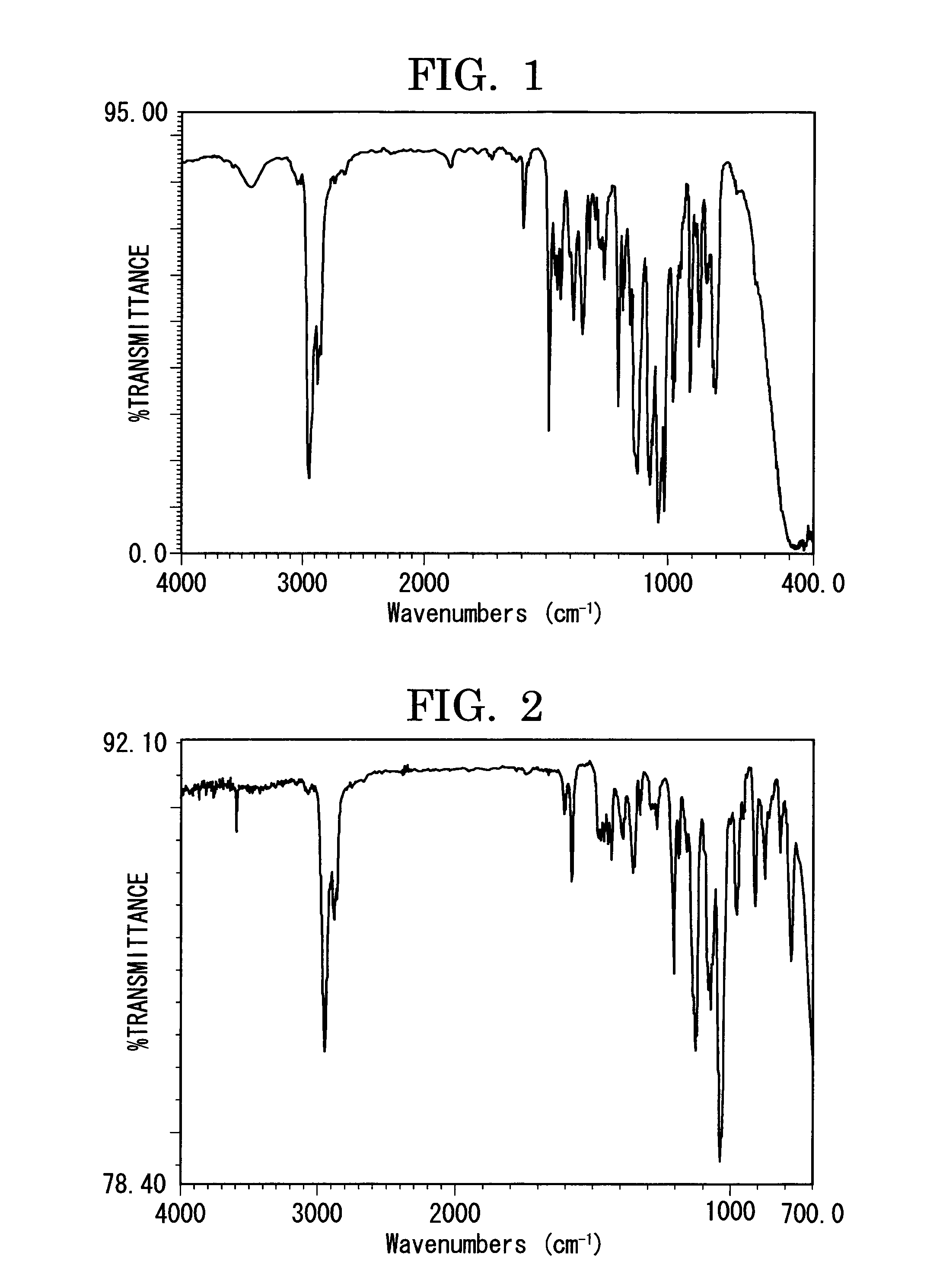
[0289]FIG. 1 shows an infrared absorption spectrum (KBr tablet method) of the compound obtained in Synthesis Example 1.

synthesis example 2

Synthesis of Halogen Intermediate

[0290]The reaction formula of Synthesis Example 2 is given below.

[0291]A four-neck flask was charged with 3-bromobenzyl alcohol (25.21 g), 3,4-dihydro-2H-pyran (22.50 g) and tetrahydrofuran (50 mL). The mixture was stirred at 5° C., and p-toluenesulfonic acid (0.259 g) was added to the four-neck flask. The resultant mixture was stirred at room temperature for 1 hour, and then extracted with ethyl acetate, dehydrated with magnesium sulfate, and adsorbed onto active clay and silica gel. The mixture was filtrated, washed and concentrated to obtain a compound of interest (yield: 36.84 g, a colorless oily product).

[0292]FIG. 2 shows an infrared absorption spectrum (KBr tablet method) of the compound obtained in Synthesis Example 2.

synthesis example 3

Synthesis of Halogen Intermediate

[0293]The reaction formula of Synthesis Example 3 is given below.

[0294]A four-neck flask was charged with 2-(4-bromobenzyl)ethylalcohol (25.05 g), 3,4-dihydro-2H-pyran (20.95 g) and tetrahydrofuran (50 mL). The mixture was stirred at 5° C., and p-toluenesulfonic acid (0.215 g) was added to the four-neck flask. The resultant mixture was stirred at room temperature for 3 hours, and then extracted with ethyl acetate, dehydrated with magnesium sulfate, and adsorbed onto active clay and silica gel. The mixture was filtrated, washed and concentrated to obtain a compound of interest (yield: 35.40 g, a colorless oily product).

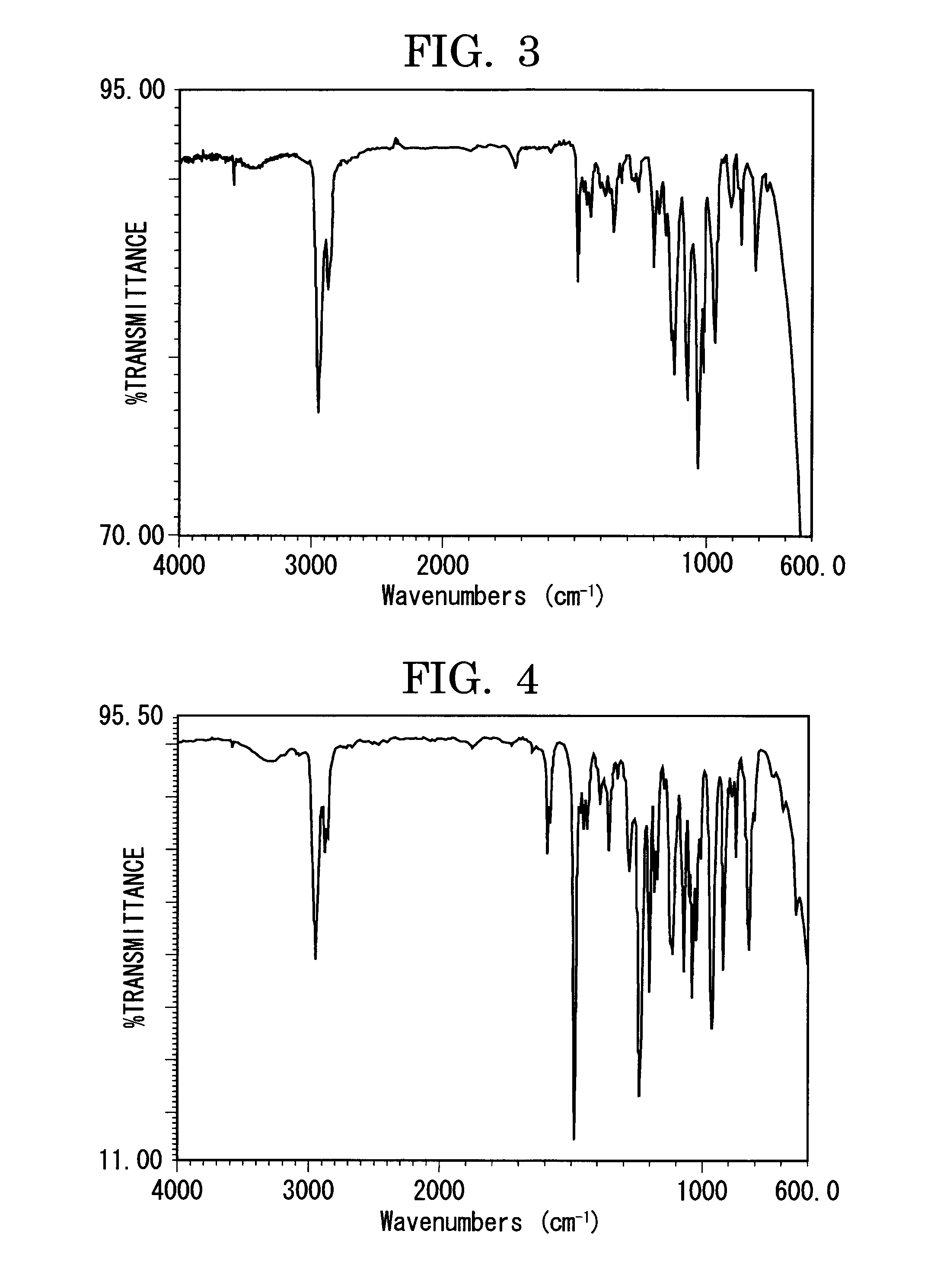
[0295]FIG. 3 shows an infrared absorption spectrum (KBr tablet method) of the compound obtained in Synthesis Example 3.


PUM

PropertyMeasurementUnit
boiling pointaaaaaaaaaa
volume resistivityaaaaaaaaaa
temperatureaaaaaaaaaa

Abstract

An electrophotographic photoconductor including: a conductive substrate; and at least a photoconductive layer on the conductive substrate, wherein an uppermost surface layer of the photoconductive layer includes a three-dimensionally crosslinked film formed through polymerization among compounds each containing a charge transporting compound and three or more [(tetrahydro-2H-pyran-2-yl)oxy]methyl groups where the charge transporting compound has one or more aromatic rings and the [(tetrahydro-2H-pyran-2-yl)oxy]methyl groups are bound to the aromatic rings of the charge transporting compound, wherein the polymerization starts after some of the [(tetrahydro-2H-pyran-2-yl)oxy]methyl groups have been partially cleaved and eliminated, and wherein the three-dimensionally cross-linked film has an ionization potential of 5.4 or higher.

Description

TECHNICAL FIELD[0001]The present invention relates to an electrophotographic photoconductor (hereinafter may be referred to as “photoconductor,”“latent electrostatic image bearing member” or “image bearing member”) having remarkably high abrasion resistance to repetitive use and having such high durability that can continue to form high-quality images with less image defects for a long period of time; and an image forming method, an image forming apparatus and a process cartridge each using the electrophotographic photoconductor.BACKGROUND ART[0002]By virtue of their various advantageous properties, organic photoconductors (OPCs) have recently been used in a lot of copiers, facsimiles, laser printers and complex machines thereof, in place of inorganic photoconductors. The reason for this includes: (1) optical characteristics such as wide light absorption wavelength range and large light absorption amount; (2) electrical characteristics such as high sensitivity and stable chargeabili...

Claims


Application Information

Patent Timeline
Patent Type & Authority Applications(United States)
IPC IPC(8): G03G15/00
CPCG03G5/07G03G5/0525G03G5/0567G03G5/0592G03G5/0596G03G5/1476G03G5/14769G03G5/14791G03G5/14795G03G5/0764G03G5/06G03G5/147
Inventor TANAKA, YUUJINAGAI, KAZUKIYOSUZUKI, TETSUROKOIZUKA, YUUSUKE
Owner RICOH KK
Learn More