Plate with contour

a technology of bone implants and contours, applied in the field of composite materials, can solve the problems of bone deterioration and resorption, stress shielding, and a relative high degree of stress, and achieve the effect of reducing friction

Inactive Publication Date: 2013-11-07
CARBOFIX ORTHOPEDICS
View PDF2 Cites 66 Cited by
  • Summary
  • Abstract
  • Description
  • Claims
  • Application Information

AI Technical Summary

Benefits of technology

[0048]a further portion formed of a hard material to strengthen the implant and / or enhance the hardness of the implant and / or to impart surface properties.
[0059]a sleeve between the fixation component and the passage. Optionally, the sleeve is configured to reduce friction between the fixation component and the passage. Optionally or alternatively, the sleeve is threaded.

Problems solved by technology

However, the rigid metal implant creates a relative high degree of stresses in certain regions of the bone, while, on the other hand, does not provide for sufficient load transfer resulting in stress shielding.
Both high stress and stress shielding can cause bone deterioration and resorption, leading to areas of bone weakness and loss of bone support for the implant (e.g., intramedullary nails and stem components of joint replacement systems).
In addition, metals may result in artifacts in CT and MR imaging.
Furthermore, metals such as stainless steel and cobalt chromium may cause biocompatibility problems related to corrosion and sensitization reaction (mainly due to allergy to nickel).
Also, conventional metal fixation components, e.g., bone-supporting components (e.g., intramedullary nails and bone plates) and pegs and screws can mask the fracture and limit the ability of the surgeon to set the fracture correctly.
Metal bone-supporting components and fixation components may also limit the ability to see the healing process in X-Rays.
Although known composite material implant technology can provide several advantages, there are also some limitations.
In contrast to metal, composite material implants are radiolucent, i.e., do not block most of the radiation coming from x-ray systems such as fluoroscopy, and hence their implantation and tracking during follow-up may be difficult.

Method used


Image

  • Plate with contour
  • Plate with contour
  • Plate with contour

Examples


Embodiment Construction

Overview of Features of Some Embodiments of the Invention

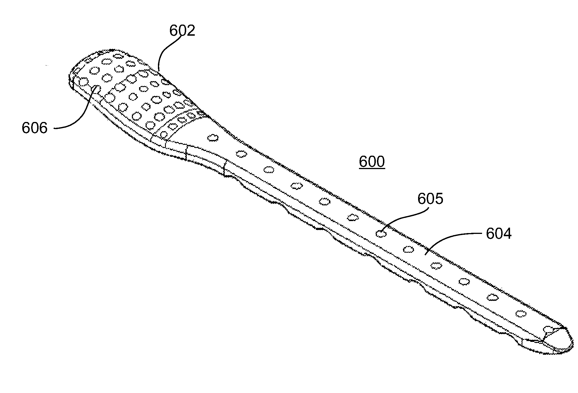
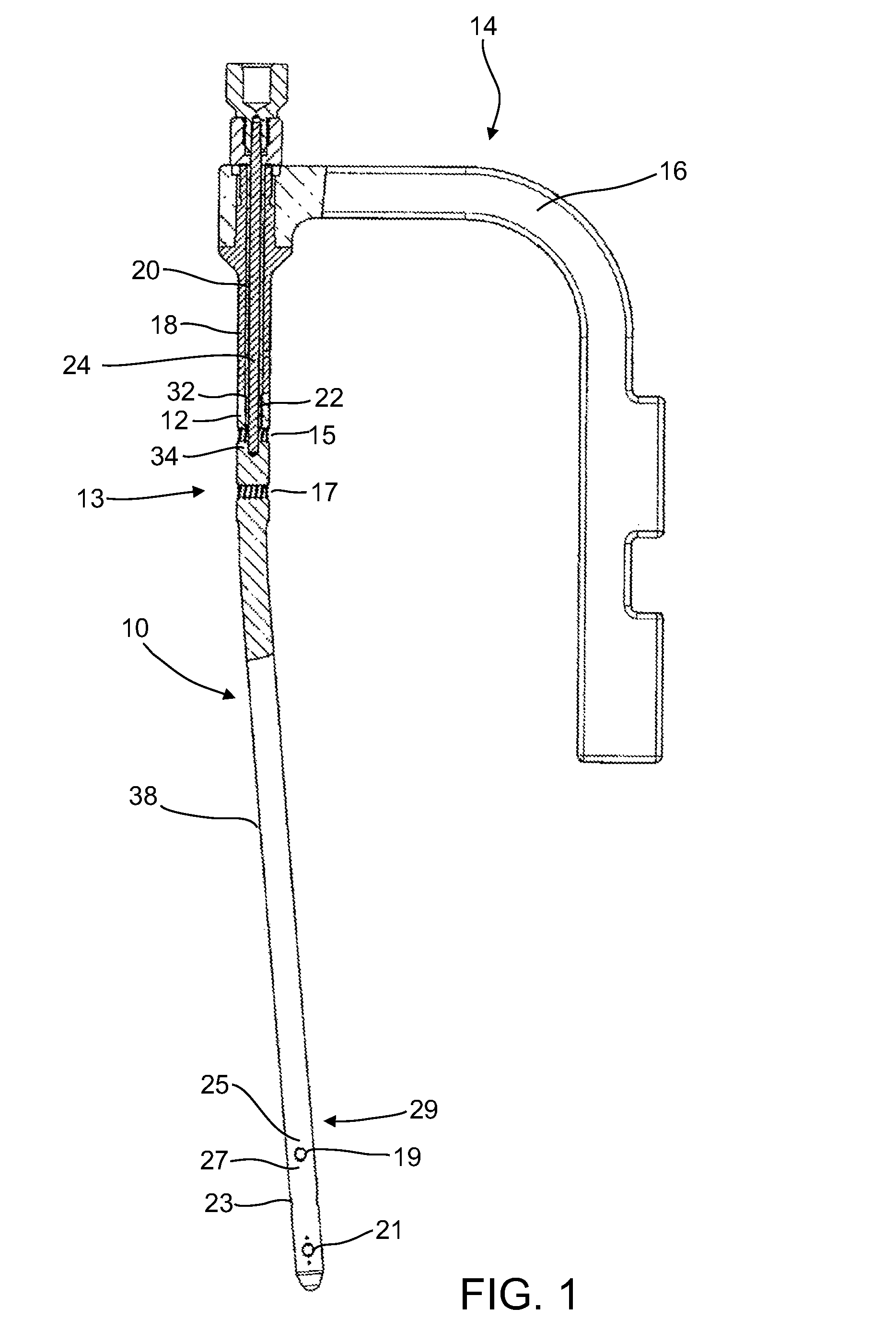
[0104]The present invention in some embodiments thereof, relates to composite material bone implant components, devices and systems, and to methods for manufacturing and using such components, devices, and systems, as well as to surgical instrumentation and procedures used during implantation. More particularly, but not exclusively, the invention relates to bone-supporting components such as bone nails and bone plates, to implant fixation components such as bone screws and pegs formed of fiber-reinforced polymer matrix composites.

[0105]In the following overview, except as otherwise indicated, it is to be understood that the implants described are all formed mainly (e.g., at least 50%, 60%, 70%, 80% or intermediate amounts of the load bearing portions thereof) of a fiber-reinforced polymer composite.

[0106]An aspect of some embodiments of the invention pertains to a bone implant component, e.g., a bone nail, a bone screw, or a p...


PUM


Abstract

A bone plate formed of a fiber-reinforced polymer composite, comprising a radiopaque marker that delineates at least a part of the contour of the plate. In some embodiments, the radiopaque marker comprises a metal wire section embedded proximal to an edge of the contour, for example at a distance of 1 mm from an edge of the contour. In some embodiments, the radiopaque marker extends along a head portion of the plate, and / or along a stem portion of the plate. In some embodiments, the metal wire is formed as an intermittent line. Alternatively, the wire is formed as a continuous line.

Description

RELATED APPLICATIONS[0001]This application is a division of U.S. patent application Ser. No. 13 / 702,334 filed on Dec. 6, 2012, which is a National Phase of PCT Patent Application No. PCT / IB2011 / 052468 having International filing date of Jun. 7, 2011, which claims the benefit of priority under 35 USC §119(e) of U.S. Provisional Patent Application Nos. 61 / 344,182 filed on Jun. 7, 2010, 61 / 443,308 filed on Feb. 16, 2011 and 61 / 486,280 filed on May 15, 2011.[0002]PCT Patent Application No. PCT / IB2011 / 052468 is also related to PCT Patent Application No. PCT / IB2010 / 050225 filed on Jan. 18, 2010.[0003]The contents of the above applications are all incorporated by reference as if fully set forth herein in their entirety.FIELD OF INVENTION[0004]The present invention in some embodiments thereof, relates to composite material bone implant components, devices and systems, and / or to methods for manufacturing and using such components, devices, and systems, and to surgical instrumentation and pro...

Claims


Application Information

Patent Timeline
Patent Type & Authority Applications(United States)
IPC IPC(8): A61B17/80A61B17/88
CPCA61B17/80A61B17/88A61B17/1728A61B17/7233A61B17/8052A61B17/8625A61B17/866A61B17/8685A61B17/8863A61B17/1717A61B17/862A61B17/863A61B2090/3966A61B17/8033A61F2210/00A61F2/28
Inventor GLOBERMAN, ORENBEYAR, MORDECHAY
Owner CARBOFIX ORTHOPEDICS
Why Eureka
Try Eureka