Repair of directionally solidified alloys

a technology of directionally solidified alloys and alloys, applied in the field of materials, can solve the problems of weakening components, limited local repairs, and difficult repair of such materials

Active Publication Date: 2013-11-14
SIEMENS ENERGY INC
View PDF5 Cites 22 Cited by
  • Summary
  • Abstract
  • Description
  • Claims
  • Application Information

AI Technical Summary

Problems solved by technology

However, repair of such materials is difficult because the repair process can destroy the directionality of the underlying crystal structure, thereby weakening the component.
While this process preserves the underlying grain structure, it is limited to local repairs having a width of 1-1,000 μm.
Furthermore, the need for a low melting temperature constituent in the solder limits the selectio

Method used


Image

  • Repair of directionally solidified alloys
  • Repair of directionally solidified alloys
  • Repair of directionally solidified alloys

Examples


Embodiment Construction

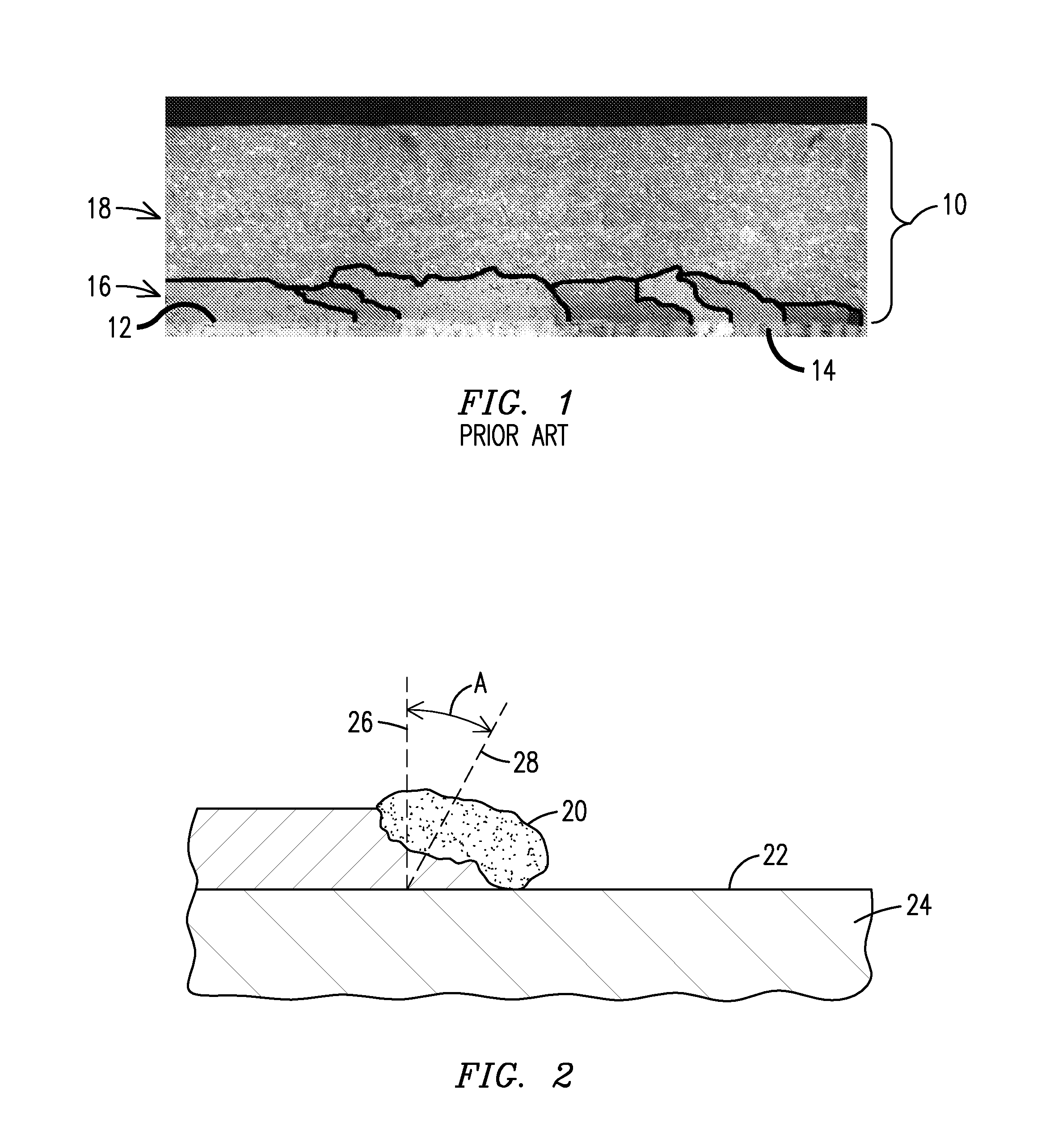
[0014]FIG. 1 is a photomicrograph illustrating the result of a typical prior art weld cladding repair, showing a multi-layer clad region 10 deposited over a surface 12 of a directionally solidified substrate material 14. In a lowermost portion 16 of the clad region 10, directionally solidified extensions of the substrate grains are highlighted in the figure with black lines. However, those grains terminate after a few layers of cladding and are covered by an uppermost portion 18 of the clad region 10 wherein recrystallization has occurred and the grains are no longer directionally solidified. The present inventor has recognized that this is the result of the local direction of process solidification achieved during the clad layering process. FIG. 2 is a schematic illustration explaining how this occurs.

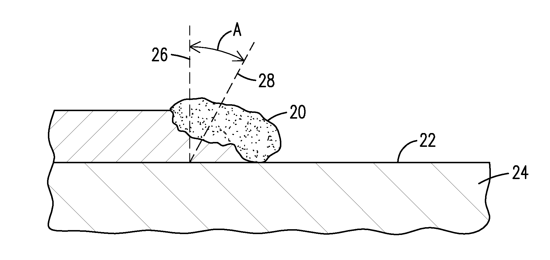
[0015]FIG. 2 shows a profile view of a melt pool 20 of clad material progressing along a surface 22 of a directionally solidified substrate 24. The grains of the substrate 24 extend i...


PUM

PropertyMeasurementUnit
Thicknessaaaaaaaaaa
Microstructureaaaaaaaaaa
Energyaaaaaaaaaa

Abstract

A method for epitaxial addition of repair material onto a process surface (38) of a directionally solidified component (30). The component is positioned in a fluidized bed (34) to drift particles of a repair material over the process surface as laser energy (36) is rastered across the surface to melt the particles and to fuse repair material onto the entire surface simultaneously. The component is moved downward (39) in the bed in a direction parallel to the grain orientation in the component as material is added to the surface, thereby providing continuous epitaxial addition of material to the surface without recrystallization.

Description

[0001]This application claims benefit of the 11 May 2012 filing date of U.S. provisional patent Application No. 61 / 645,800.FIELD OF THE INVENTION[0002]The invention relates generally to the field of materials, and more specifically to the repair of directionally solidified alloys.BACKGROUND OF THE INVENTION[0003]High temperature, high stress machine applications such as gas turbine engines have required the development of nickel and cobalt based superalloys. Components formed of such alloys may be cast to be equiaxed (random polycrystalline structure), or to be columnar grained (crystal grains formed parallel to a major stress axis), or to be a single crystal (no grain boundaries). Columnar grained and single crystal structures are formed by directionally solidifying molten alloy material during the casting process, and such structures can provide performance benefits for certain applications.[0004]It is desired to repair a directionally solidified superalloy component rather than t...

Claims


Application Information

Patent Timeline
IPC IPC(8): B05D3/06
CPCB23K26/34F01D5/005F05D2230/31F05D2300/606B23K26/32B23K26/342B23K2103/50F01D5/00Y02T50/60
Inventor BRUCK, GERALD J.
Owner SIEMENS ENERGY INC
Why Eureka
Try Eureka