Non-contact Sludge Drying System With Flue Gas Heat

a drying system and flue gas technology, applied in drying machines, lighting and heating apparatus, combustion types, etc., can solve the problems of reducing affecting the efficiency of sludge drying, so as to reduce the energy consumption of sludge and maximize the use of flue gas heat

Inactive Publication Date: 2013-11-21
SHANGHAI FUBO ENVIRONMENTAL PROTECTION EQUIP
View PDF8 Cites 16 Cited by
  • Summary
  • Abstract
  • Description
  • Claims
  • Application Information

AI Technical Summary

Benefits of technology

[0019]Through the foregoing technical solutions, the non-contact sludge drying system with flue gas heat of the present invention is different from other drying systems directly enabling the flue gas to contact the sludge, which first converts the boiler flue gas heat into vapor, hot water, or hot wind, and then heats the sludge with the vapor, the hot water, or the hot wind to dry the sludge, and maximizes the use of the flue gas heat in the case of avoiding the flue gas acid dew corrosion, thereby reducing the energy consumption in the sludge drying and decreasing the operation cost of the sludge drying.

Problems solved by technology

However, the sludge treatment manners all have strict requirements on the water content of the sludge.
Such a manner has high utilization of the heat energy; however, if the dried material has a degree of polluting, the problems regarding the emission are incurred; as the entering of high-temperature flue gas is continuous, the waste gas with the equivalent flow and directly contacted the material has to be exhausted after special treatment.
The indirect use results in a certain degree of heat loss.
For the drying process, the direct or the indirect heating results in different loss of thermal efficiency, and has different effects on the environment.
The flue gas of this part generally dews when the gas temperature is lower than that of the acid dew point, to corrode the heat exchanger, which is a problem cannot be avoided in both the direct drying and the indirect drying.
For the contact drying directly using flue gas, in addition to the problem of acid dew corrosion, the flue gas already used to dry the sludge needs to be treated again, which incurs a high volume of the flue gas and has a high treatment cost.

Method used


Image

  • Non-contact Sludge Drying System With Flue Gas Heat
  • Non-contact Sludge Drying System With Flue Gas Heat
  • Non-contact Sludge Drying System With Flue Gas Heat

Examples


Embodiment Construction

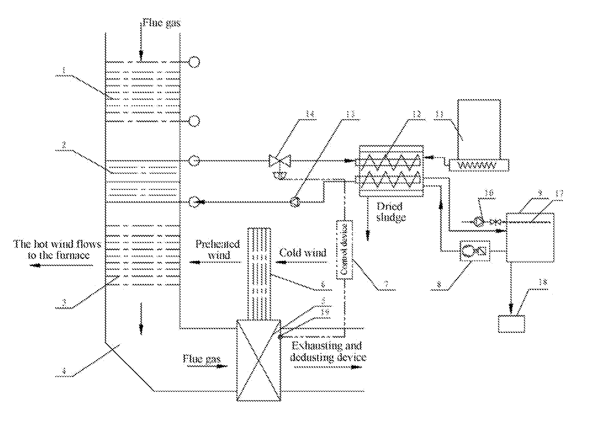
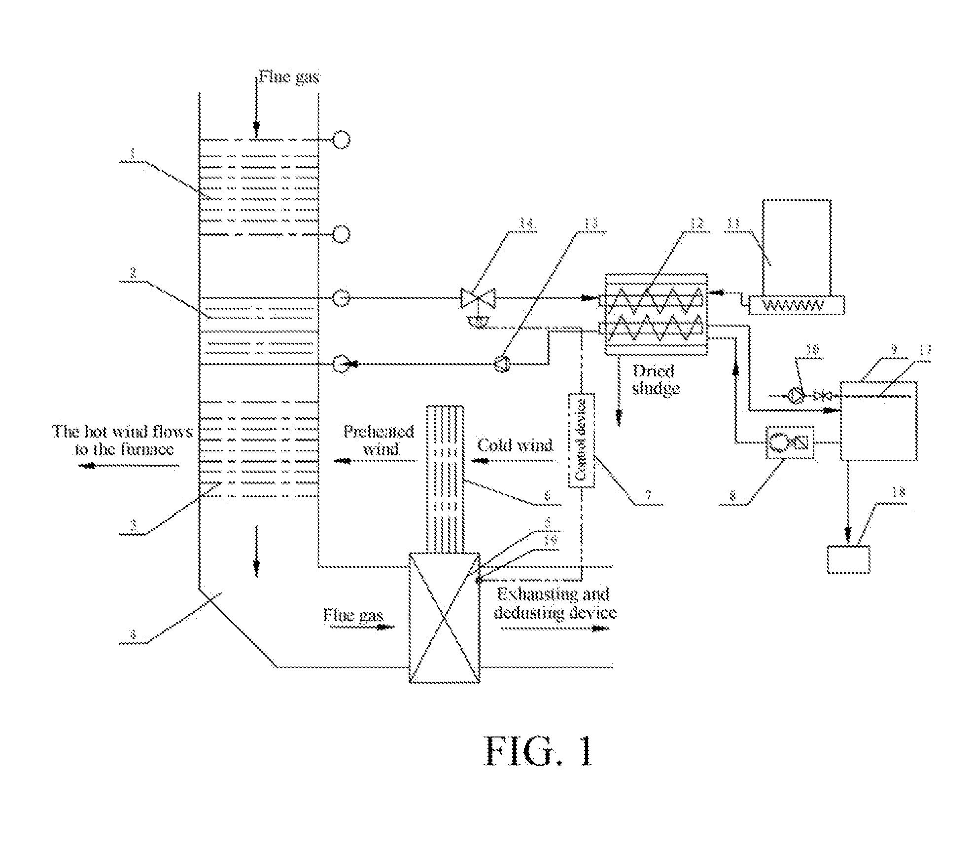
[0023]The non-contact sludge drying system with flue gas heat of the present invention is described in detail below with reference to the specific embodiments.

[0024]As shown in FIG. 1, a specific embodiment of a non-contact sludge drying system with flue gas heat according to the present invention is provided, in which the sludge is dried by using vapor and hot water as a heat transfer medium. The system includes a sludge bin 11 and a dryer 12 that are successively connected, and further includes an economizer 1, a high-temperature flue gas heat recovery device 2, and an air preheater 3 that are successively disposed in a boiler tail flue 4 along a flue gas flowing direction. The high-temperature flue gas heat recovery device 2 is connected to a heater in the dryer by a circulation pipe, a heat transfer medium is disposed in the circulation pipe, and a heat transfer medium driving device and an electric control valve 14 are disposed on the circulation pipe. The heat transfer medium ...


PUM


Abstract

A non-contact sludge drying system with flue gas heat according to the present invention includes a dryer, and further includes an economizer, a high-temperature flue gas heat recovery device, and an air preheater that are successively disposed in the flue along a flue gas flowing direction. A heater is disposed in the dryer, the high-temperature flue gas heat recovery device is connected to the heater by a circulation pipe, a heat transfer medium is disposed in the circulation pipe, a heat transfer medium driving device is disposed on the circulation pipe, and the dryer is connected to a sludge vapor recovery system. The non-contact sludge drying system with flue gas heat according to the present invention uses the flue gas heat from a thermal power plant boiler or another industrial boiler as a heat source to further dehydrate and dry the dehydrated sludge of the sewage treatment plant, so that the dried sludge can be used as a fuel with certain heat of combustion or composted for further treatment.

Description

BACKGROUND OF THE INVENTION[0001]1. Field of Invention[0002]The present invention relates to the environmental protection industry regarding boilers and sludge, and more specifically to a non-contact sludge drying system with flue gas heat.[0003]2. Description of Related Arts[0004]Sludge is produced in a procedure of treating sewage by the urban sewage treatment plant, the chemical plant, and the paper mill, and the amount thereof accounts for about 0.5%-0.7% of the total sewage treatment capacity. After simple treatment, the water content of the sludge is about 80%-85%. With the continuous development of national economy, the requirements on the environment become increasingly high. The treatment rate of the sewage across the country is increasingly improved, and the number of the built and the operating sewage treatment plants is continuously increased, resulting in rapidly growing sludge production. According to incomplete statistics, at present, the sewage treatment capacity in ...

Claims


Application Information

Patent Timeline
Patent Type & Authority Applications(United States)
IPC IPC(8): F26B23/00
CPCF26B23/001C02F11/13F23G5/04F23G7/001F26B2200/18Y02P70/10
Inventor QIAN, XUELUE
Owner SHANGHAI FUBO ENVIRONMENTAL PROTECTION EQUIP
Why Eureka
Try Eureka