Garnet-type crystal for scintillator and radiation detector using the same

a technology of radiation detector and graphite crystal, which is applied in the direction of conversion screens, instruments, nuclear engineering, etc., to achieve the effects of high density, short fluorescence life time, and high degree of energy resolution

Active Publication Date: 2013-11-21
FURUKAWA COMPANY +1
View PDF5 Cites 18 Cited by
  • Summary
  • Abstract
  • Description
  • Claims
  • Application Information

AI Technical Summary

Benefits of technology

[0017]According to the present invention, there is provided a garnet-type crystal for a scintillator that is suitably applicable to radia...

Problems solved by technology

However, in the technique of Patent Document 1, a peak emission wavelength is as short as not being longer than 350 nm and ...

Method used


Image

  • Garnet-type crystal for scintillator and radiation detector using the same
  • Garnet-type crystal for scintillator and radiation detector using the same
  • Garnet-type crystal for scintillator and radiation detector using the same

Examples


examples

[0087]Hereinafter, specific examples of the present invention will be described in detail with reference to drawings, but the present invention is not limited thereto. Moreover, in the following examples, a Ce concentration is described as a concentration in a specific crystal or as a concentration in a (charged) melt. However, in the respective examples, there is relationship in which the concentration at the time of charging is about 1 to 10 relative to 1 as a concentration in a crystal.

example a1

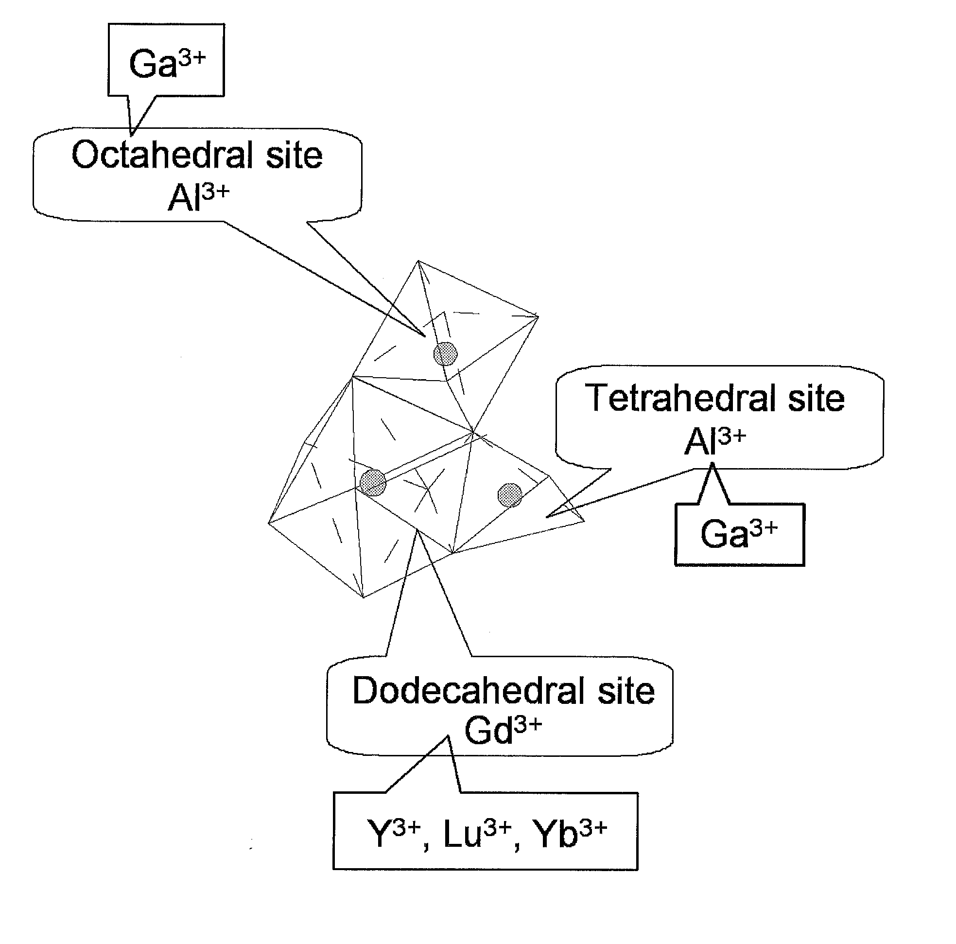
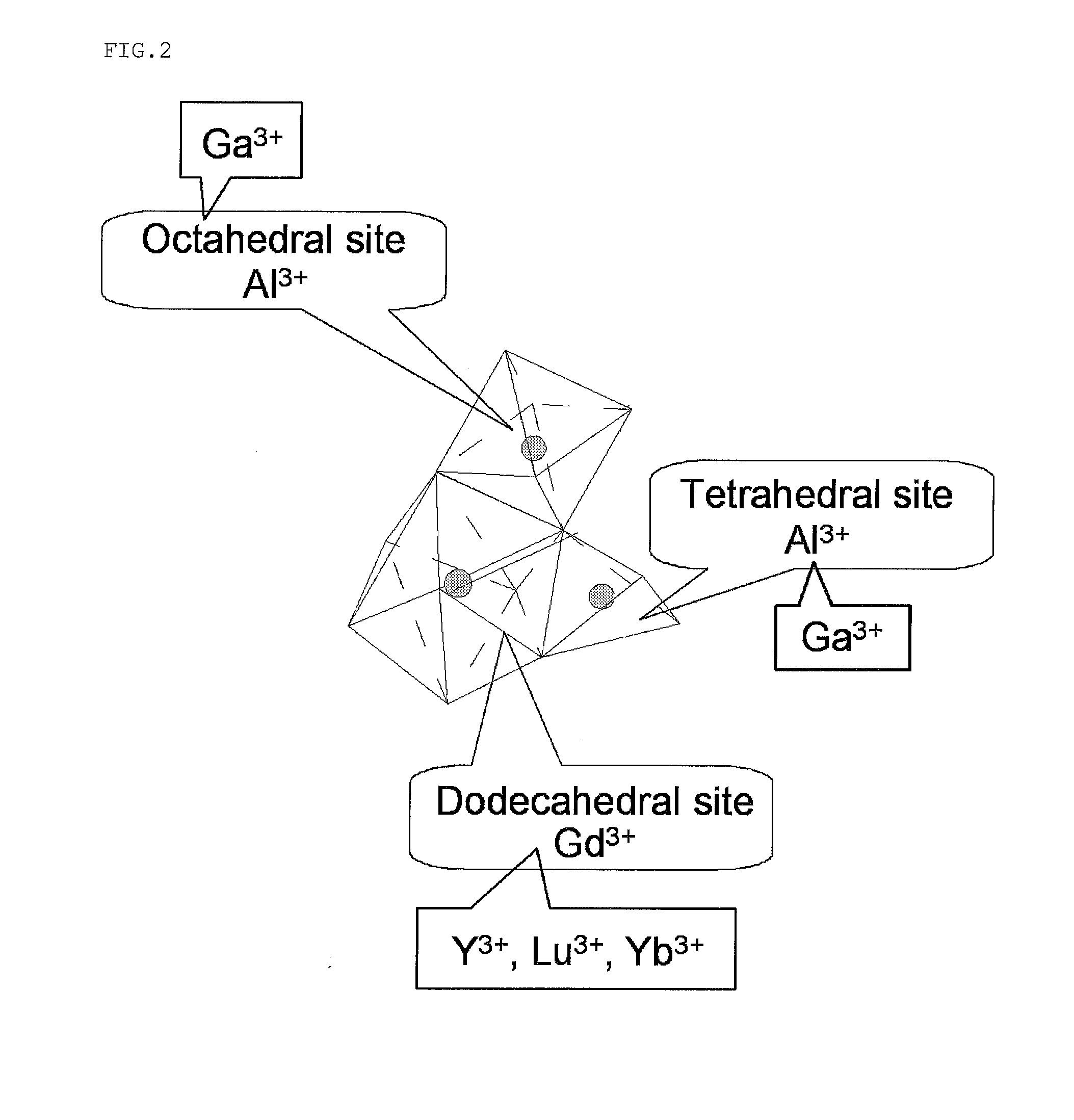
[0088]By a micro-pulling-down method, a garnet-type crystal represented by a composition of Gd2.997Ce0.003Ga2.2Al2.8O12 was prepared.

example a2

[0089]By a micro-pulling-down method, a garnet-type crystal represented by a composition of Gd2.997Ce0.003Ga3Al2O12 was prepared.


PUM


Abstract

The garnet-type crystal for a scintillator of the present invention is represented by General Formula (1), (2), or (3),
Gd3-x-yCexREyAl5-zGazO12  (1)
wherein in Formula (1), 0.0001≦x≦0.15, 0≦y≦0.1, 2<z≦4.5, and RE represents at least one selected from Y, Yb, and Lu;
Gd3-a-bCeaLubAl5-cGacO12  (2)
wherein in Formula (2), 0.0001≦a≦0.15, 0.1<b≦3, and 2<c≦4.5;
Gd3-p-qCerRE′qAl5-rGarO12  (3)
wherein in Formula (3), 0.0001≦p≦0.15, 0.1<q≦3, 1<r≦4.5, and RE′ represents Y or Yb.

Description

TECHNICAL FIELD[0001]The present invention relates to a garnet-type crystal for a scintillator and a radiation detector using the same.BACKGROUND ART[0002]A scintillator single crystal is used for a radiation detector that detects a γ-ray, X-ray, α-ray, β-ray, neutron ray, and the like. Such a radiation detector is being widely applied to medical imaging devices such as a Positron Emission Tomography (PET) device and an X-ray Computerized Tomography (CT) device, various radiation measurement devices in the field of high energy physics, resource exploration devices, and the like. The radiation detector is generally constituted with a scintillator that absorbs the γ-ray, X-ray, α-ray, β-ray, neutron ray, and the like and converts these into plural low-energy photons (scintillation light) and a light-receiving element that receives the luminescence from the scintillator and converts the light into electric signals. In the diagnosis of cancer that uses the Positron Emission Tomography (...

Claims


Application Information

Patent Timeline
IPC IPC(8): C09K11/77G01T1/202
CPCC09K11/7769G01T1/2023C09K11/7774G01T1/202G21K4/00C09K11/7706G01T1/249
Inventor YOSHIKAWA, AKIRAYANAGIDA, TAKAYUKIKAMADA, KEISATO, HIROKITSUTSUMI, KOSUKEENDO, TAKANORIITO, SHIGEKI
Owner FURUKAWA COMPANY
Why Eureka
Try Eureka