However, increasing
motor speed creates a number of design issues to overcome that primarily occur in two areas, being the motor itself and
electrical control of the motor.
For the motor itself, the design issues would include
structural integrity of the motor rotor to withstand high rotational speeds, motor rotor shaft bearings again to withstand high rotational speeds, clearances as between static and dynamic parts, and temperature rise considerations due to friction and electrical inefficiencies which become predominate at
higher power densities, as smaller motor size equates to lower surface areas and lower volumes to absorb and shed heat buildup.
A conventional lower rotational speed motor rotor construction (typically termed squirrel cage induction), utilizes a complex multi piece built-up rotor with iron plates and
copper wire windings-being limited to a maximum rotational speed of about twenty thousand
revolutions per minute (20,000 rpm) due to rotational centrifugal stress and excessive heat buildup in the iron and
copper due to electrical inefficiency.
Although the permanent
magnet reduces the previously mentioned electrical inefficiency of the squirrel cage induction rotor, the addition of the structural reinforcement that is positioned between the high speed motor rotor and
stator increases electrical inefficiency as the structural reinforcement acts as an electrical and
physical barrier between the rotor permanent
magnet and the rotating
electromagnetic field of the
stator.
The
Hall effect sensor works well, however, having drawbacks of size and structure needed to accommodate the sensor in proximity to the motor rotor plus the need for an asymmetrical discontinuity in the rotor to give the sensor a “read” section for
rotor speed and position.
The requirements of the sensor and asymmetrical discontinuity are generally not desirable in the high speed motor for several reasons; the sensor structure consumes
physical space which on a proportional scale is problematic in a smaller high speed motor, plus in addition, the asymmetrical discontinuity in the rotor also consumes
physical space and further interferes with achieving optimal rotor balance and causes added stress in the rotor, wherein desirable design in a high speed motor would dictate minimal
physical structure space consumed and minimal rotor size that is completely symmetric in design.
One sensorless high speed motor solution is to use motor back
electromotive force (EMF) as a way to determine motor
rotor speed and rotor position while the motor is operational—i.e. the rotor is rotating, however, having the problems that no back EMF is generated when the motor rotor is stopped, which can lead to rotor
position error at motor startup, which could cause reverse rotor rotation.
In contrast to this requirement, several loss mechanisms with the controller and motor are tied to the frequency content of the current waveforms, with losses tending to rise with increasing frequency or increased motor rotational speed.
The problem with this is that it results in high switching losses and limits upon the motor rotational speed achievable.
This of course brings in a complication as this
metal “can” or could be termed a structural reinforcement sleeve needs to have fairly high strength in a tensile manner and also have high electrical resistivity to minimize
eddy current losses during BLDC motor operation.
The
sine wave controller with prior art
sine wave filters is typically large, expensive, and inefficient with a limited optimum speed range.
Utilizing simple block commutation as previously described with a high-speed
metal structural sleeve banded motor rotor results in current waveforms and subsequent motor
air gap flux profiles that cause excessive rotor heating and thus motor inefficiency.
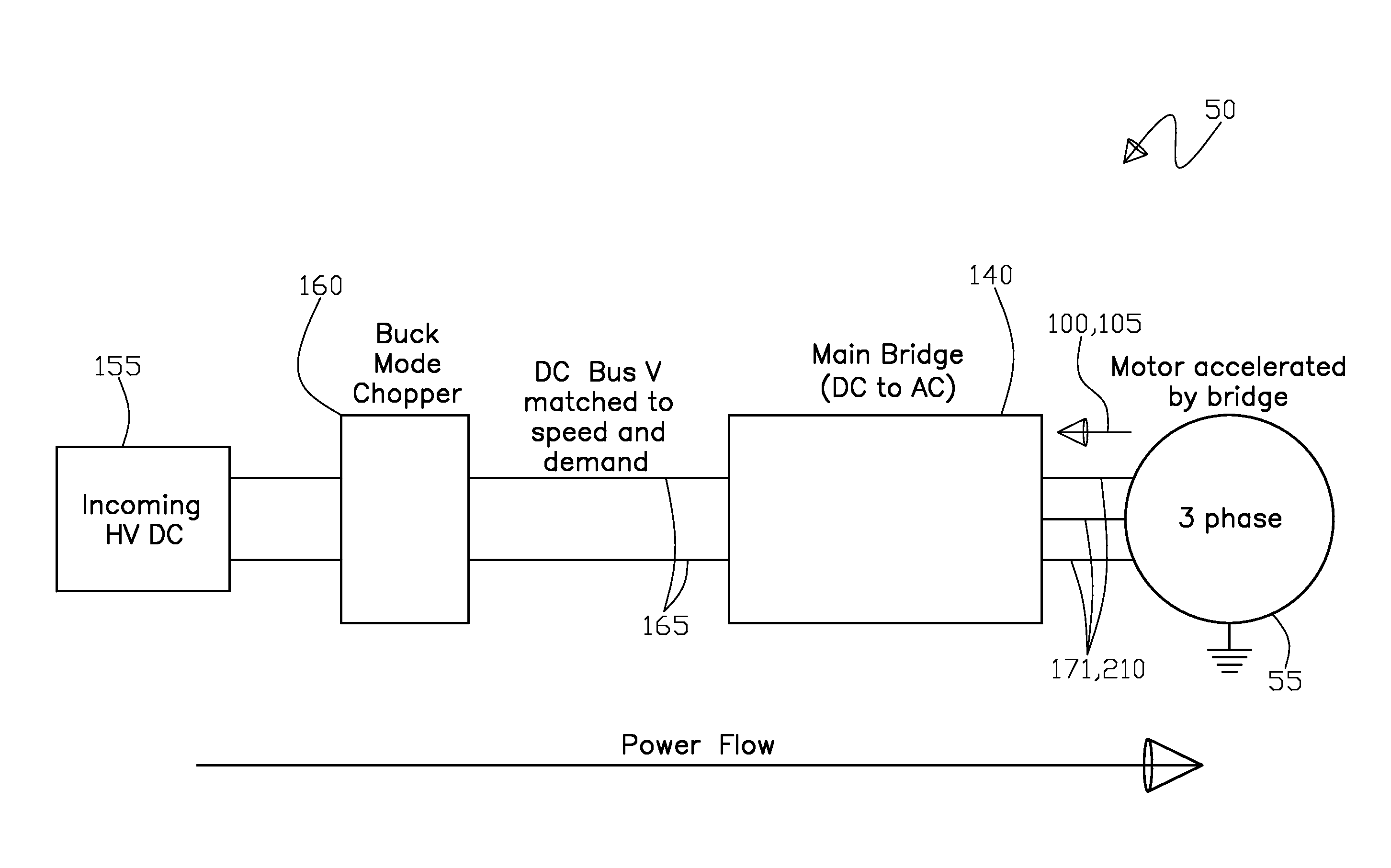
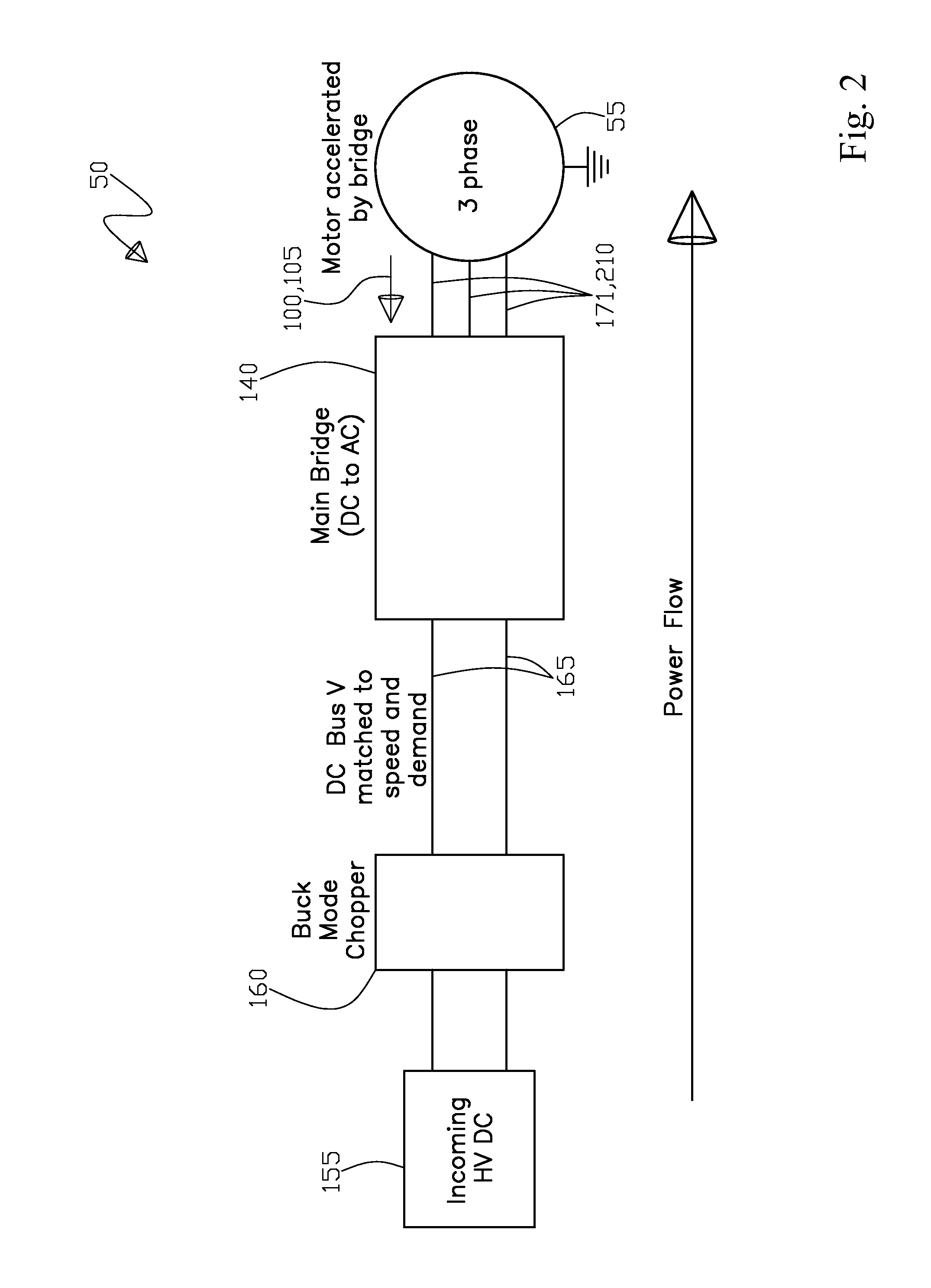
The difficulty with maintaining this condition is that the required voltage changes with every change to the desired speed of the motor output shaft and further with a shaft load at that speed, thus being a very dynamic condition.
In addition, this operating mode will dramatically limit the available power at a low
motor shaft output speed due to the
linear relationship between speed and output voltage.

