Porous Scaffolds for Hydrogen Fuel in Inertial Confinement Fusion Capsules

Inactive Publication Date: 2013-11-21
LAWRENCE LIVERMORE NAT SECURITY LLC
View PDF13 Cites 16 Cited by
  • Summary
  • Abstract
  • Description
  • Claims
  • Application Information

AI Technical Summary

Benefits of technology

[0014]In the present invention, a nanoporous scaffold is used for both (i) symmetrizing the hydrogen fuel inside the ICF capsule and (ii)

Problems solved by technology

A challenge of the fabrication of such liquid DT targets relates to the formation of low-den

Method used


Image

  • Porous Scaffolds for Hydrogen Fuel in Inertial Confinement Fusion Capsules
  • Porous Scaffolds for Hydrogen Fuel in Inertial Confinement Fusion Capsules
  • Porous Scaffolds for Hydrogen Fuel in Inertial Confinement Fusion Capsules

Examples


Embodiment Construction

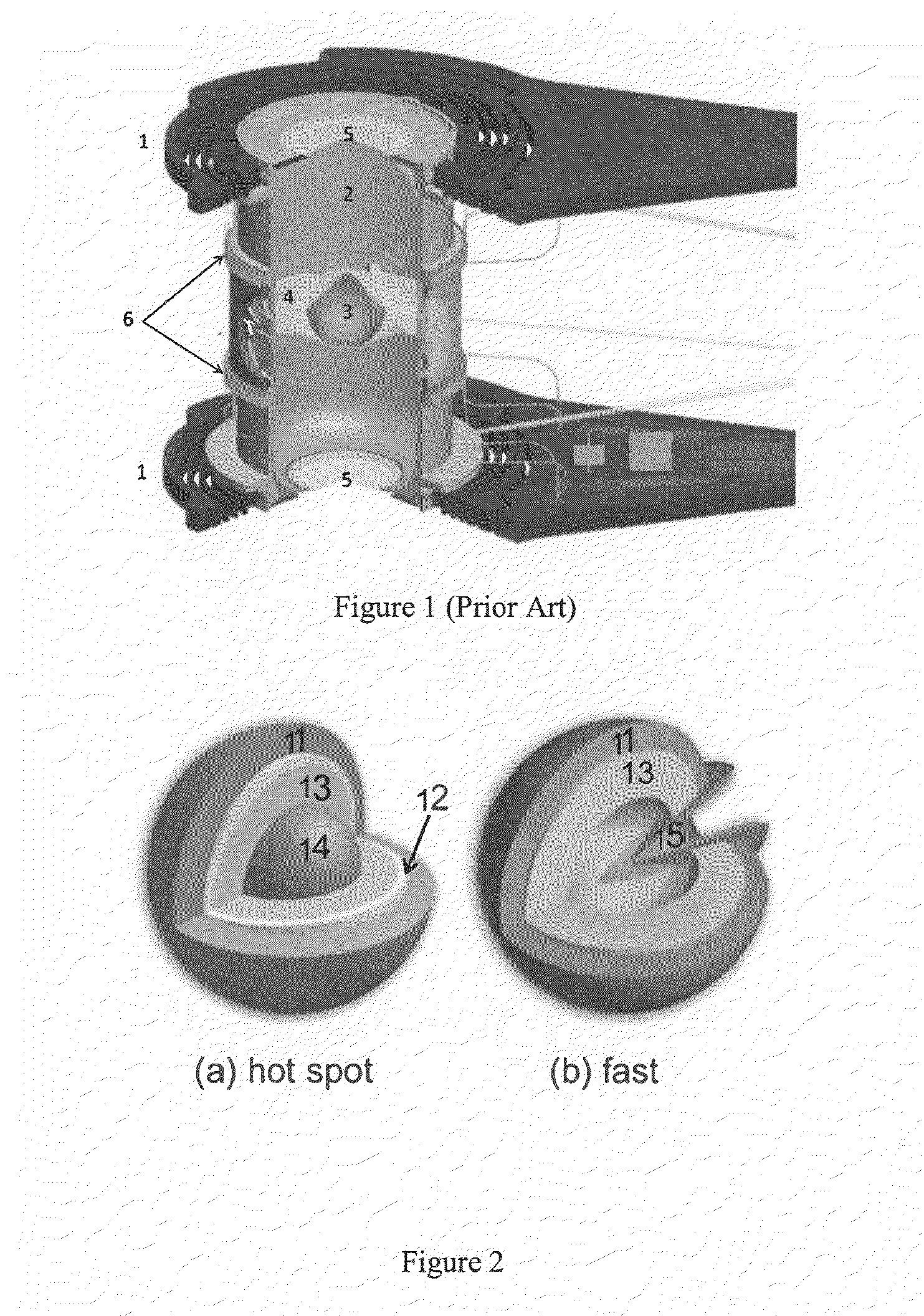
[0024]FIG. 1 illustrates a prior art ICF fuel target assembly for hot-spot ignition experiments at the National Ignition Facility. The components illustrated include cryocooling single-crystal silicon arms 1 connected to the cold finger of a cryostat and a gold hohlraum 2. A fuel capsule 3 having a beryllium metal, carbon, or plastic ablator shell with an outer diameter of about 2 mm is positioned in the center of the hohlraum 2. It is supported there by about 10-100-nm-thick polymer “tents”4, which center and hold the ablator shell in the hohlraum 2. Laser entrance holes 5 at each end of the hohlraum 2 are sealed with about 500-nm-thick polymer films. Heaters 6 control the growth and uniformity of the solid hydrogen (DT) fuel layer (not shown) inside of the ablator shell of the capsule 3. In the NIF experiments, laser beams enter the hohlraum through the laser entrance holes 5, irradiating the interior of the hohlraum 2. X-rays from the hohlraum 5 then strike the fuel capsule 3 and...


PUM

PropertyMeasurementUnit
Thicknessaaaaaaaaaa
Thicknessaaaaaaaaaa
Thicknessaaaaaaaaaa

Abstract

A fusion fuel capsule is disclosed having a substantially spherical ablator shell. The interior surface of the shell is lined with a nanoporous scaffold layer wetted with either a fully or partially liquid mixture of deuterium and tritium.

Description

REFERENCE TO RELATED APPLICATION[0001]This application claims priority from U.S. Provisional Patent Application entitled “Porous Scaffolds for Hydrogen Fuel Layering of Inertial Confinement Fusion Targets,” U.S. Application No. 61 / 558,990, filed Nov. 11, 2011, which is incorporated herein by reference in its entirety.STATEMENT AS TO RIGHTS TO INVENTIONS MADE UNDER FEDERALLY SPONSORED RESEARCH OR DEVELOPMENT[0002]The United States Government has rights in this invention pursuant to Contract No. DE-AC52-07NA27344 between the United States Department of Energy and Lawrence Livermore National Security, LLC.BACKGROUND OF THE INVENTION[0003]For many decades, thermonuclear fusion power, in either pure fusion or fission-fusion hybrid reactors, has been envisioned as a viable solution for future world's energy demands. In such reactors, energy is harvested from nuclear fusion reactions of light nuclei such as deuterium (D) and tritium (T) hydrogen isotopes. This invention relates to capsules...

Claims


Application Information

Patent Timeline
IPC IPC(8): G21B1/19
CPCG21B1/19B82Y15/00B82Y30/00Y02E30/10
Inventor KUCHEYEV, SERGEI O.
Owner LAWRENCE LIVERMORE NAT SECURITY LLC
Why Eureka
Try Eureka