
Carbon and carbon/silicon composite nanostructured materials and casting formation method

Active Publication Date: 2013-11-21
RGT UNIV OF CALIFORNIA
View PDF3 Cites 6 Cited by
  • Summary
  • Abstract
  • Description
  • Claims
  • Application Information

AI Technical Summary

Benefits of technology

This patent describes a method of creating materials with precise photonic responses using nanostructured composite materials. The materials can be in the form of films or particles, and they are made by introducing a carbon precursor into the pores of a porous silicon film. Carbon is then formed, resulting in a material with a unique photonic response determined by the pattern in the porous silicon template. The method can produce materials with high precision and can be used to create optical devices with controlled optical properties.

Problems solved by technology

For example, freshly prepared porous silicon possesses a silicon hydride terminated surface; however, this surface is not environmentally stable and it does not provide strong adsorption sites for many organic molecules.
These adsorption characteristics place a fundamental limit on the sensitivity of the device.
Previously reported chemical modification reactions for porous silicon surfaces suffer from incomplete coverage and poor thermal or environmental stability.

Method used


Image

  • Carbon and carbon/silicon composite nanostructured materials and casting formation method
  • Carbon and carbon/silicon composite nanostructured materials and casting formation method
  • Carbon and carbon/silicon composite nanostructured materials and casting formation method

Examples


Embodiment Construction

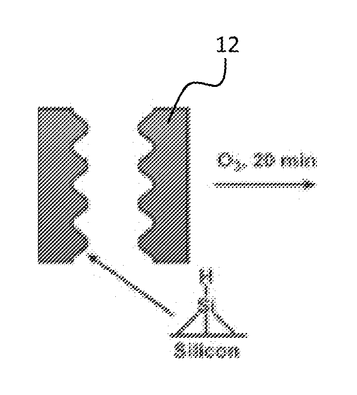
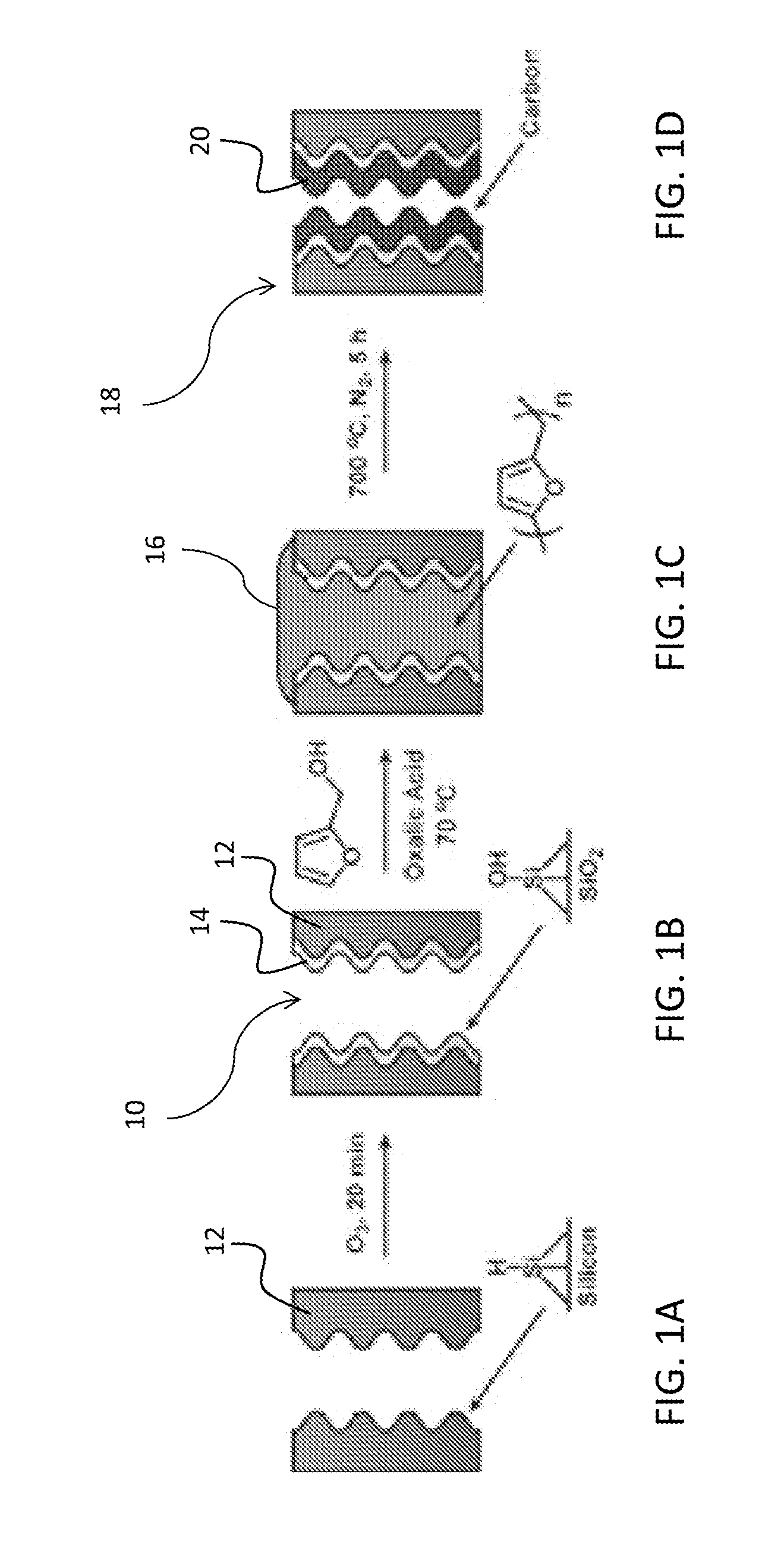
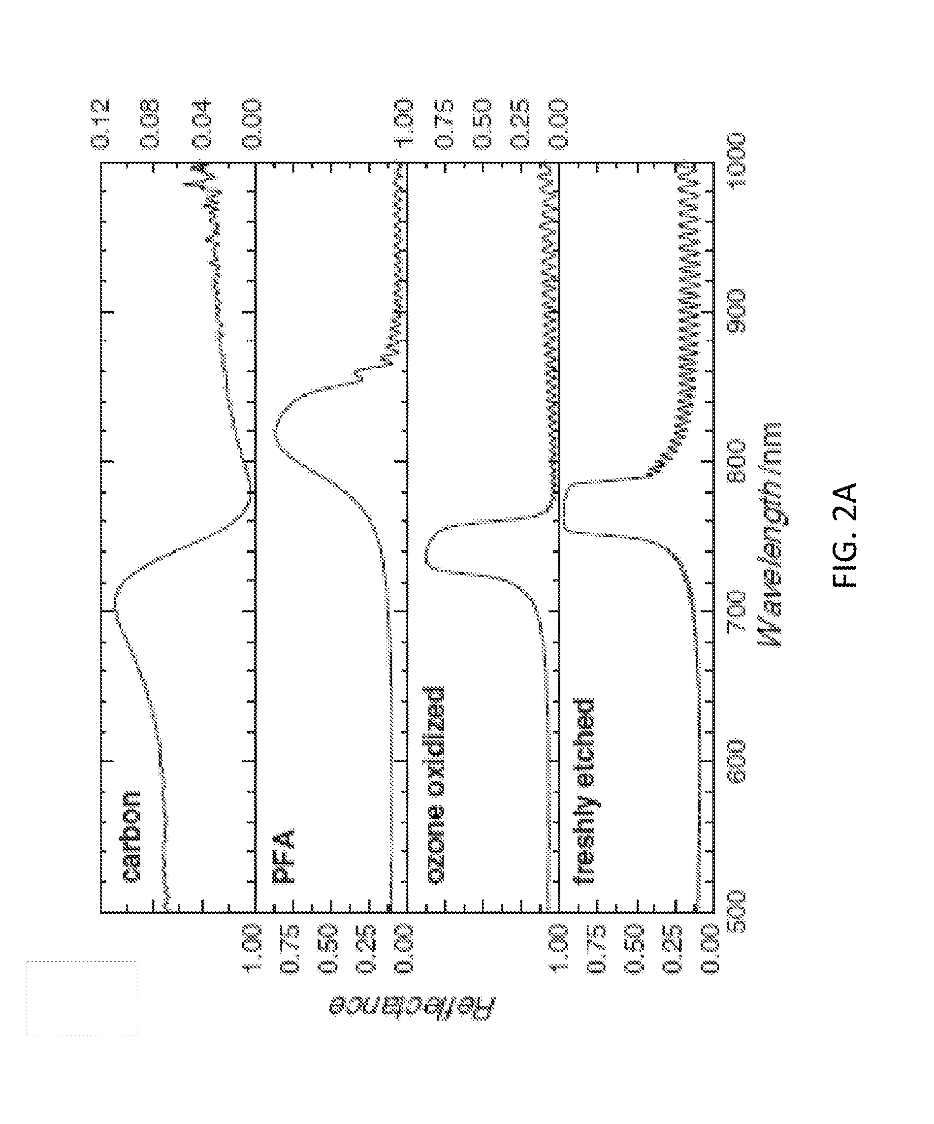
[0016]Preferred embodiment nanostructured materials of the invention include nanostructured carbon / silicon composites and carbon nanofiber arrays. Composites and carbon material of the invention can include photonic structures. Preferred embodiments methods of the invention synthesize nanostructured carbon inside the pores of a porous silicon template by a polymerization and carbonization procedure. In particular preferred embodiments, the porous silicon template is oxidized prior to the polymerization and carbonization procedure, though those procedures can also be conducted on freshly etched porous silicon. Free-standing nanofiber structured carbon can be obtained by dissolution of the porous silicon template. The carbon nanofibers adopt the shape and morphology of the porous silicon template, and can provide a photonic nanostructured material that is stable in liquid. Particles of nanostructured carbon are formed by drying the film. Carbon / silicon composite particles can also be ...


PUM


Abstract

The invention provides nanostructure composite porous silicon and carbon materials, and also provides carbon nanofiber arrays having a photonic response in the form of films or particles. Composite materials or carbon nanofiber arrays of the invention are produced by a templating method of the invention, and the resultant nanomaterials have a predetermined photonic response determined by the pattern in the porous silicon template, which is determined by etching conditions for forming the porous silicon. Example nanostructures include rugate filters, single layer structures and double layer structures. In a preferred method of the invention, a carbon precursor is introduced into the pores of a porous silicon film. Carbon is then formed from the carbon precursor. In a preferred method of the invention, liquid carbon-containing polymer precursor is introduced into the pores of an porous silicon film The precursor is thermally polymerized to form a carbon-containing polymer in the pores of the porous silicon film, which is then thermally carbonized to produce the nano structured composite material. A carbon nanofiber array is obtained by dissolving the porous silicon. A carbon nanofiber array can be maintained as a film in liquid, and particles can be formed by drying the material.

Description

PRIORITY CLAIM AND REFERENCE TO RELATED APPLICATION[0001]The application claims priority under 35 U.S.C. §119 from prior provisional application Ser. No. 61 / 378,566, which was filed on Sep. 29, 2010.STATEMENT OF GOVERNMENT INTEREST[0002]This invention was made with government support under DMR-0806859 awarded by National Science Foundation. The government has certain rights in the invention.FIELD[0003]A field of the invention is carbon fiber composites and sensors, free-standing carbon nanostructures, carbon photonic sensors and fabrication methods for composite and free-standing nanostructured carbon. Example applications of composite and free standing nanostructured carbon include remote chemical sensing, air quality monitoring, water quality monitoring, biosensors, pre-concentrators, electrode materials (e.g., for Li-ion batteries or supercapacitors), field-emission arrays, electromagnetic shielding components.BACKGROUND[0004]Previous generations of sensors for chemical or biolog...

Claims


Application Information

Patent Timeline
IPC IPC(8): C01B31/02
CPCC01B31/0226D01D5/00D01F9/14G02B1/005Y10T428/2918C01B31/022B82Y30/00B82Y40/00B82B1/00C01B32/16C01B32/166Y10T428/249994
Inventor SAILOR, MICHAEL J.KELLY, TIMOTHY
Owner RGT UNIV OF CALIFORNIA
Learn More