
Decomposition of residual data during signal encoding, decoding and reconstruction in a tiered hierarchy

a technology of residual data and signal encoding, applied in the direction of color television with bandwidth reduction, television systems, instruments, etc., can solve the problems of large portion of available processing power going unused, higher resolution images including a higher amount of camera noise and/or film grain, and achieve the effect of maintaining the efficiency advantage of leveraging and improving the efficiency of residual encoding and decoding

Active Publication Date: 2013-11-28
V NOVA INT LTD
View PDF6 Cites 26 Cited by
  • Summary
  • Abstract
  • Description
  • Claims
  • Application Information

AI Technical Summary

Benefits of technology

This patent describes a new method for efficiently encoding image data using residual data. The method uses a decomposition transform to transform the residual data and leverage the correlation among the residues. The transformed data is then quantized and encoded using a low complexity, parallel, scalable, and error control encoding method. The resulting encoded data has a smaller size and higher efficiency. The method also allows for a lossless transform and effectively deal with correlations among the residues. Overall, this method provides a more efficient and effective way to encode image data.

Problems solved by technology

Thus, a large portion of available processing power may go unused when implementing MPEG-like types of encoding / decoding, with blocking artifacts needlessly introduced into the signal.
This makes the use of frequency-domain transforms such as those used in JPEG-based and MPEG-based methods even more unsuitable for image processing and playback, since the range of relevant frequencies is getting much broader.
In addition, higher resolution images include a higher amount of camera noise and / or film grain, i.e., very detailed high-frequency pixel transitions that require many bits to encode, but that can be quite irrelevant for viewing vs. similar high-frequency pixel transitions of borders of objects.
Another aspect neglected in the known art, aside from few attempts, is the quality scalability requirement.
Scalability has been taken into consideration in known methods like MPEG-SVC and JPEG2000, with relatively poor adoption so far due to computational complexity and, generally speaking, compression inefficiency relatively to non-scalable techniques.
Use of conventional Laplacian pyramid encoding has been abandoned, due to their compression inefficiency.
First of all, the very choice of transforming into a frequency domain makes them unsuitable to properly exploit the correlation across large portions of a signal (i.e., portions with a high number of samples for each of the dimensions), since real-world signals typically show limited amounts of periodicity. As a consequence, frequency domain transforms are performed on blocks that are at the same time too big and too small: too big to be computationally simple, too small to sufficiently exploit the correlation of a high-resolution signal. For instance, in order to exploit the correlation of a large enough set of samples while at the same time managing computational complexities, conventional image and video encoding techniques operate on blocks of 8×8, 16×16 or 32×32 elements: clearly too small to fully capture the correlation of image patterns in a high definition image (e.g., with 8 million pixels), but large enough to absorb significant computational power.
Secondly, known methods leveraging frequency domain transforms implicitly assume that humans are sensitive to harmonics (e.g., frequencies of color transitions) in a way that does not depend on the direction of the transition, while several studies have shown that humans recognize the sharpness of a transition much better than the precise direction / angle of the transition, especially when watching complex shapes.
Third, known lossy encoding techniques operate by quantizing the results of the transform, inevitably generating two problems: (1) block-based artifacts between one block and the neighboring ones, to be corrected with relatively complex de-blocking image processing methods; (2) impossibility to easily control the maximum error in an encoded image, since actual pixel values are the result of an inverse transform of de-quantized parameters, so that quantization errors in the quantized parameters of a block combine with one another in manners that are difficult to manage without multiple re-encodings and / or extremely complex quantization schemes. Avoiding block artifacts and guaranteeing maximum error control are particularly important features, especially in applications such as medical imaging or professional image / video production.

Method used


Image

  • Decomposition of residual data during signal encoding, decoding and reconstruction in a tiered hierarchy
  • Decomposition of residual data during signal encoding, decoding and reconstruction in a tiered hierarchy
  • Decomposition of residual data during signal encoding, decoding and reconstruction in a tiered hierarchy

Examples


Embodiment Construction

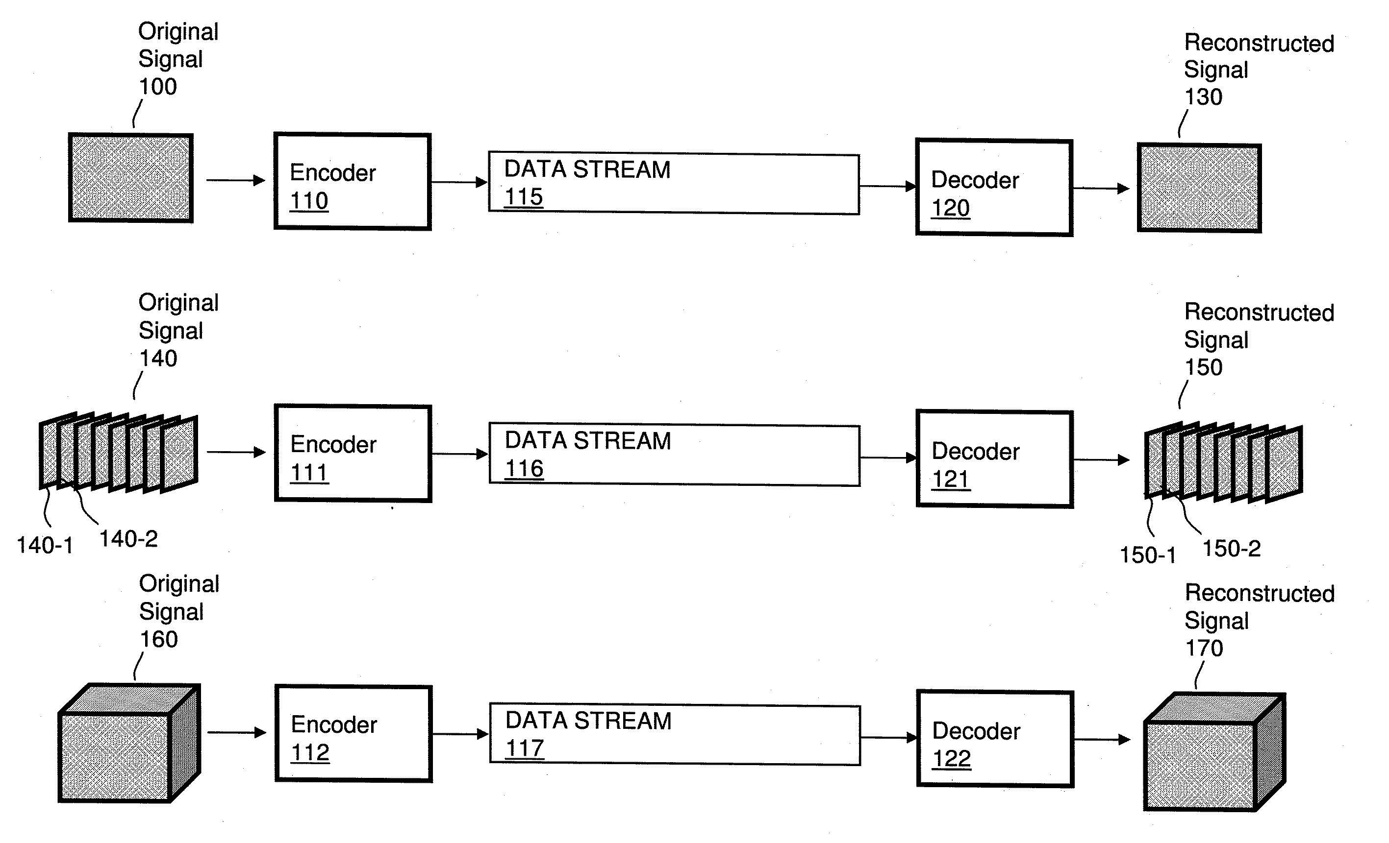
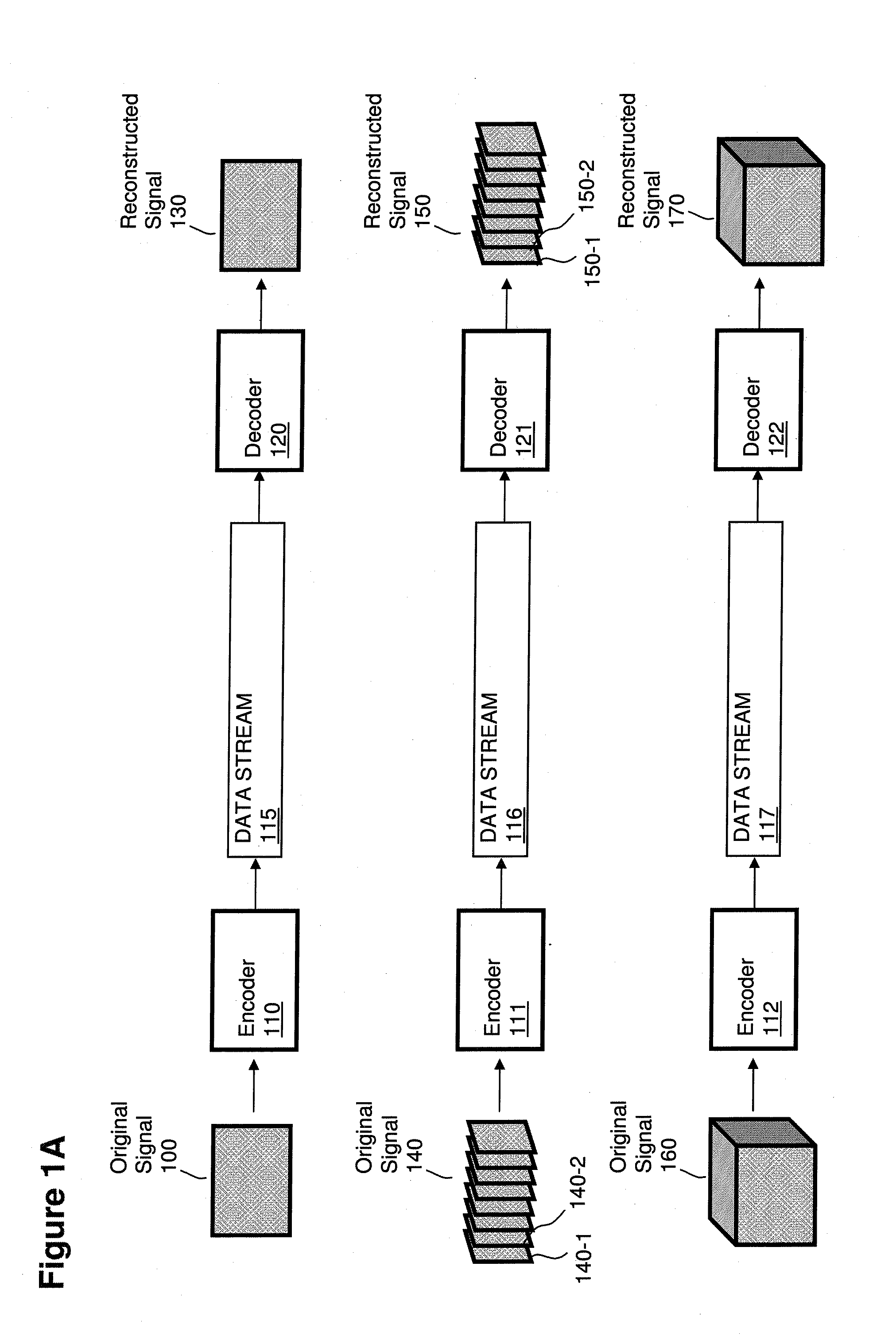
[0080]Methods illustrated herein are suitable for any type of multi-dimensional signals, including without limitation sound signals, multichannel sound signals, pictures, two-dimensional images, video signals, multi-view video signals, 3D video signals, volumetric signals, volumetric video signals, medical imaging signals, signals with more than four dimensions, etc.

[0081]For simplicity, along the description the illustrated embodiments usually adopt the use case of 2D images (e.g., either isolated pictures or frames / fields of a video signal), with each element (in such non-limiting example case typically referred to as a “pixel”, more in general referred to as “per”) being characterized by a set of color or other parameter settings in a suitable color space (e.g., YUV, RGB, HSV, etc.). Different color planes (e.g., the luminance-Y plane and the two chrominance—U and V—planes) are often encoded separately, and often with different resolutions (due to the lower sensitivity of the hum...


PUM


Abstract

Computer processor hardware receives a first set of adjustment values. The first set of adjustment values specify adjustments to be made to a predicted rendition of a signal generated at a first level of quality to reconstruct a rendition of the signal at the first level of quality. The computer processor hardware processes the first set of adjustment values and derives a second set of adjustment values based on the first set of adjustment values and a rendition of the signal at a second level of quality. The second level of quality is lower than the first level of quality.

Description

RELATED APPLICATIONS[0001]This application is related and claims the benefit of U.S. Provisional Patent Application Ser. No. 61 / 646,797 entitled “SIGNAL ENCODING, DECODING AND RECONSTRUCTION OF TIME-BASED AND / OR MULTIDIMENSIONAL SIGNALS BASED ON MULTIDIMENSIONAL TIER-BASED INHERITANCE” (Attorney Docket No. VNO12-01p), filed on May 14, 2012, the entire teachings of which are incorporated herein by this reference.[0002]This application is related to and claims the benefit of U.S. Provisional Patent Application Ser. No. 61 / 647,426 entitled “ESTIMATION, ENCODING, DECODING AND USAGE OF MOTION INFORMATION IN MULTIDIMENSIONAL SIGNALS THROUGH MOTION ZONES, MOTION MATRIXES, WARP MAPS AND MOTION TRANSFORMS” (Attorney Docket No. VNO12-02p), filed on May 15, 2012, the entire teachings of which are incorporated herein by this reference.[0003]This application is also related to U.S. patent application Ser. No. 13 / 188,188 entitled “INHERITANCE IN A TIERED SIGNAL QUALITY HIERARCHY,” (Attorney Docke...

Claims


Application Information

Patent Timeline
IPC IPC(8): H04N7/26H04N19/94
CPCH04N19/00909H04N19/63H04N19/62H04N19/635H04N19/23H04N19/33H04N19/87H04N19/94H04N19/59H04N19/126H04N19/30H04N19/42H04N19/439G06T7/248H04N19/70H04N19/50H04N19/51H04N19/40H04N19/57H04N19/573G06T9/00G06T9/40H04N5/145H04N19/136
Inventor ROSSATO, LUCAMEARDI, GUIDO
Owner V NOVA INT LTD
Learn More