Light assembly for remote visual inspection apparatus

a technology for visual inspection and assembly, which is applied in the field of remote visual inspection devices, can solve the problems of inefficient high intensity discharge lamps, large amount of heat, and easy to break, rupture and sudden failure, and is easy to be turned on and o

Inactive Publication Date: 2013-11-28
GE INSPECTION TECH LP
View PDF39 Cites 117 Cited by
  • Summary
  • Abstract
  • Description
  • Claims
  • Application Information

AI Technical Summary

Benefits of technology

[0014]FIG. 10 is a block electrical layout diagram of a remote visual inspection apparatus electrical and control system;

Problems solved by technology

Inspection units for remotely inspecting the interior portions of a body cavity of a living thing, such as a person, for medical diagnosis or a medical procedure, or for inspection or possibly repair of interior portions of industrial equipment, such as a boiler, a pipe or an engine, are known: Such devices commonly employ inefficient high intensity discharge lamps, e.g. xenon, high pressure mercury, or metal halide lamps that generate a significant amount of heat and are susceptible to breaking, rupture and sudden failure.
High intensity discharge lamps are incapable of readily being turned on and off as needed by an inspector, further increasing their inefficiency and impairing their utility.
However, using light emitting diodes in the distal end of the device has also been problematic in that such an arrangement produces undesired heat within both the distal end of the remote visual inspection device, and the target area on which the inspection is taking place.
The use of multiple LEDs requires a significant amount of physical space and limits the ability to miniaturize inspection devices for insertion into small, confined spaces.
Further limitations occur as multiple inefficient LEDs reduce the gains that LEDs can provide.
However, placement of the LED in a proximal position also results in inefficiencies because of the inherent loss associated with focusing the broad angular emission of an LED onto an optical fiber.
These systems, as described, have deficiencies in aspects such as efficiency, portability and convenience that are general needs in the industry.

Method used


Image

  • Light assembly for remote visual inspection apparatus
  • Light assembly for remote visual inspection apparatus
  • Light assembly for remote visual inspection apparatus

Examples


Embodiment Construction

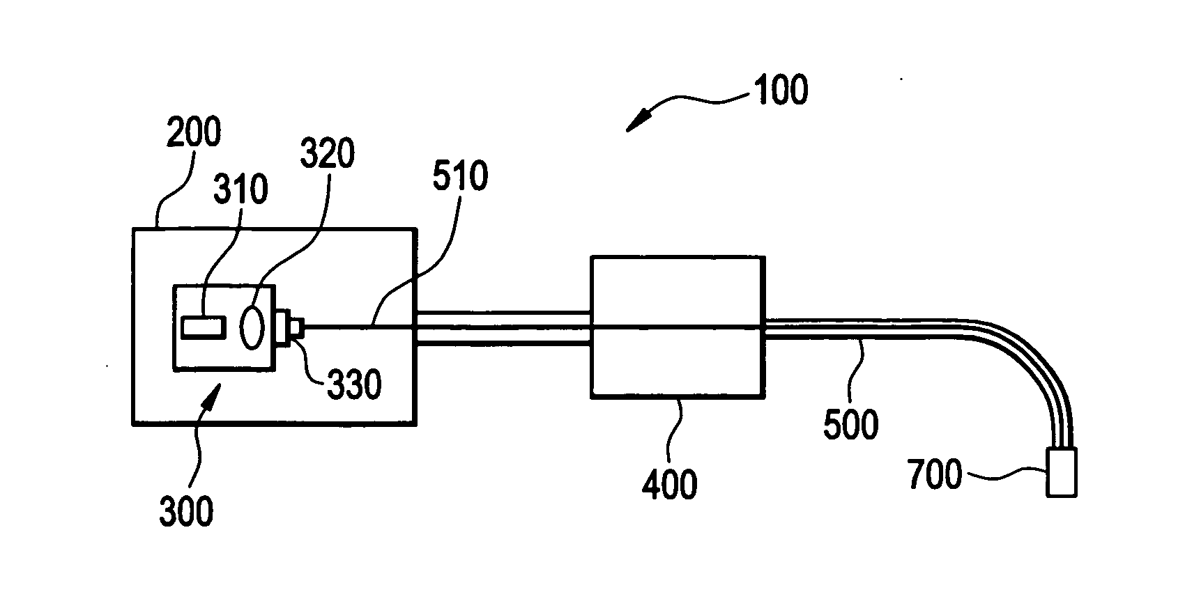
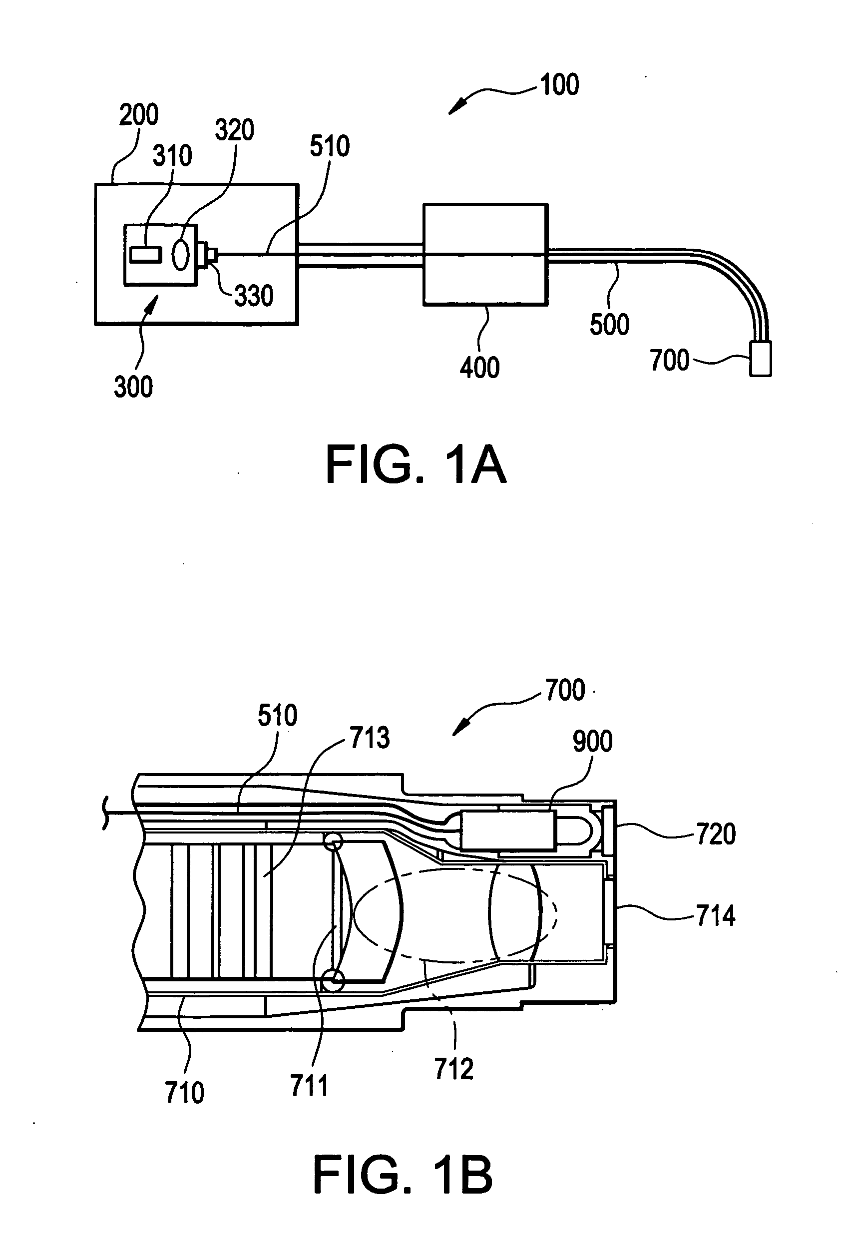
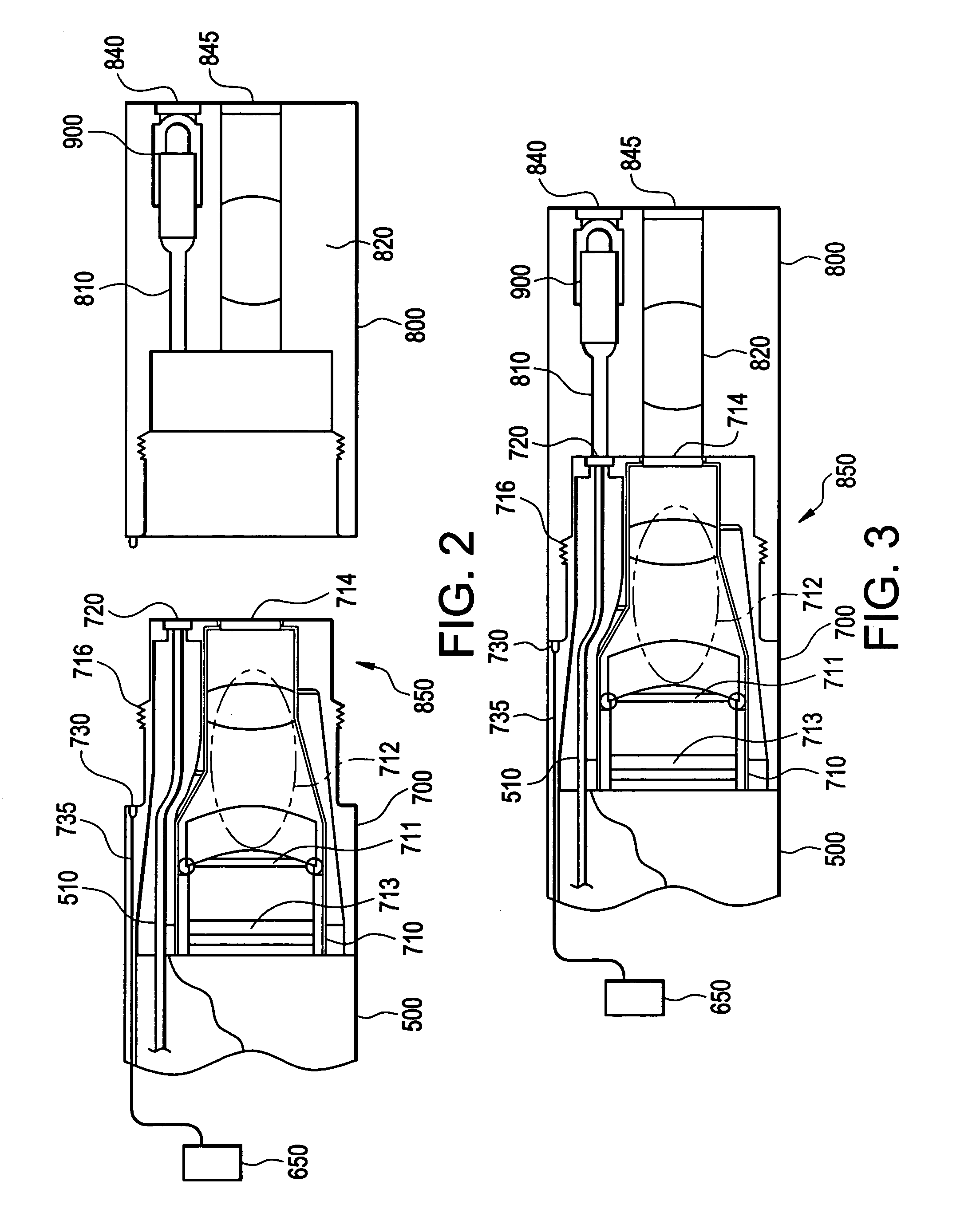
[0017]As discussed in detail below, there is provided in one embodiment a low power illumination system comprising a light source directing light onto a fiber optic bundle that carries light to a distal section having an optical diffuser. The light source can be a laser diode assembly. Use of the laser diode can reduce power consumption to between 1 and 3 Watts, as opposed to 24 to 75 Watts when using a high intensity discharge lamp. Reduced power consumption results, in turn, in lower heat generation and increased efficiency of the remote visual inspection apparatus. In addition, use of a laser diode provides an inspector with wide latitude to turn the illumination source of the remote visual inspection apparatus on and off as a given inspection situation requires, thereby increasing the overall efficiency of the device. In one embodiment, the optical diffuser can be provided by a wavelength converter which, in addition to diffusing light, converts the wavelength of received light ...


PUM


Abstract

An apparatus for use as a light assembly in remote visual inspection devices is provided. The light assembly may consist of a laser diode coupled to a fiber optic bundle that transmits collimated laser light onto a wavelength converter located in the distal end of the remote video inspection system. Wavelength converters consisting of phosphorescent materials can be used to convert collimated laser light into white light for inspection illumination purposes.

Description

FIELD OF THE INVENTION[0001]This invention relates generally to remote visual inspection devices, and, in particular, to a light assembly for use in remote visual inspection devices.BACKGROUND OF THE INVENTION[0002]Inspection units for remotely inspecting the interior portions of a body cavity of a living thing, such as a person, for medical diagnosis or a medical procedure, or for inspection or possibly repair of interior portions of industrial equipment, such as a boiler, a pipe or an engine, are known: Such devices commonly employ inefficient high intensity discharge lamps, e.g. xenon, high pressure mercury, or metal halide lamps that generate a significant amount of heat and are susceptible to breaking, rupture and sudden failure. High intensity discharge lamps are incapable of readily being turned on and off as needed by an inspector, further increasing their inefficiency and impairing their utility.[0003]One approach used to resolve the deficiencies in utilizing high intensity...

Claims


Application Information

Patent Timeline
Patent Type & Authority Applications(United States)
IPC IPC(8): A61B1/06A61B1/07A61B1/05
CPCA61B1/0653A61B1/05A61B1/07A61B1/00165A61B1/0638G02B23/2469A61B1/00096A61B1/00101A61B1/0684A61B1/00179A61B1/0615A61B1/063H04N23/555H04N23/56
Inventor MORSE, BRADFORD
Owner GE INSPECTION TECH LP
Why Eureka
Try Eureka