
System and method for traction motor control

a technology of traction motor and system, applied in the field of motor control, can solve the problems of reducing or losing the adhesion of all vehicle wheels to the surface, slowing the vehicle's motion, and excessive slippage of all vehicle wheels, so as to prevent the wheel from large slippage overshoots and reduce the value of accelerating torqu

Active Publication Date: 2013-12-05
GE GLOBAL SOURCING LLC
View PDF43 Cites 10 Cited by
  • Summary
  • Abstract
  • Description
  • Claims
  • Application Information

AI Technical Summary

Benefits of technology

The patent text describes a method for controlling a traction motor in a vehicle to prevent the wheel from overshooting during acceleration. This is achieved by restricting the rate at which the excitation frequency of the motor can change once the wheel creep threshold is exceeded. This results in a reduced value of accelerating torque, preventing the wheel from large creep overshoots, and utilizing the motor's characteristic of reducing the gain (motor torque) to counter the naturally occurring creep gain in wheeled vehicles. The technical effect of this method is to improve the vehicle's stability and efficiency during acceleration.

Problems solved by technology

In this mode of operation, the traction motors exert torque in an opposite direction from the rolling direction of the wheels, thereby slowing the vehicle's motion.
Operation of any or all wheels away from the optimum creep, e.g., at too small a creep value or too large a creep value, may result in a reduction or loss of wheel-to-surface adhesion.
Likewise, if the wheel-to-surface adhesion tends to be reduced or lost, some or all the vehicle wheels may slip excessively, i.e., the actual slip speed or creep may be greater than the optimum creep.
Such a wheel slip condition, which is characterized in the motoring mode by one or more slipping axle-wheel sets and in the braking mode by one or more sliding or skidding axle-wheel sets, can cause accelerated wheel wear, rail damage, high mechanical stresses in the drive components of the propulsion system, and an undesirable decrease of tractive (or braking) effort.
However, especially at low speeds, creep regulators have an increasingly more difficult time regulating wheel speeds.
This leads to large overshoots in wheel speed, rapid torque reductions, and torque reapplication limit cycles.
This may result in high wheel creep transients capable of damaging the rail head (in the case of a rail vehicle), reduced tractive effort, rapid suspension displacements, poor vehicle ride quality, and vehicle reference speed errors.

Method used


Image

  • System and method for traction motor control
  • System and method for traction motor control
  • System and method for traction motor control

Examples


Embodiment Construction

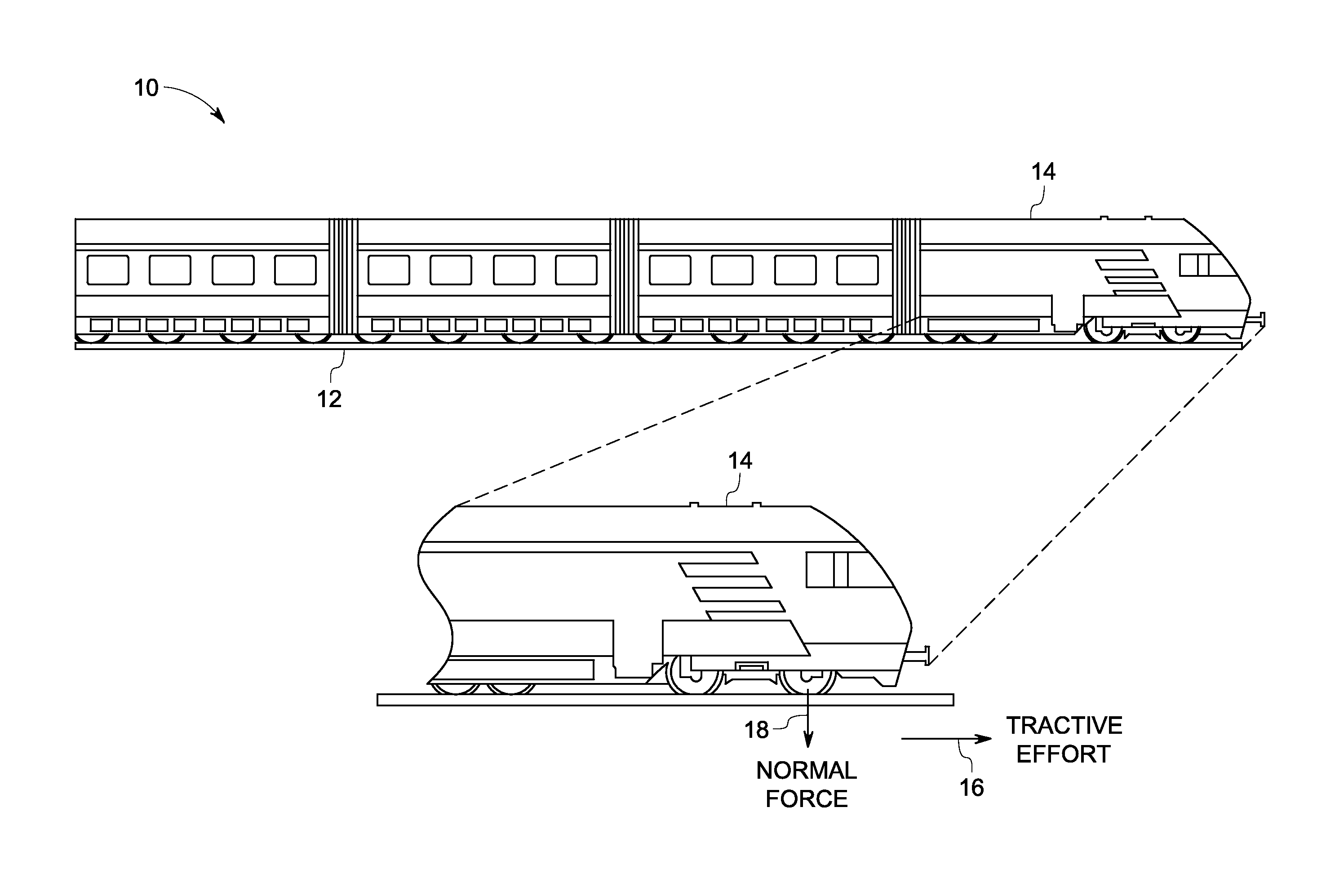
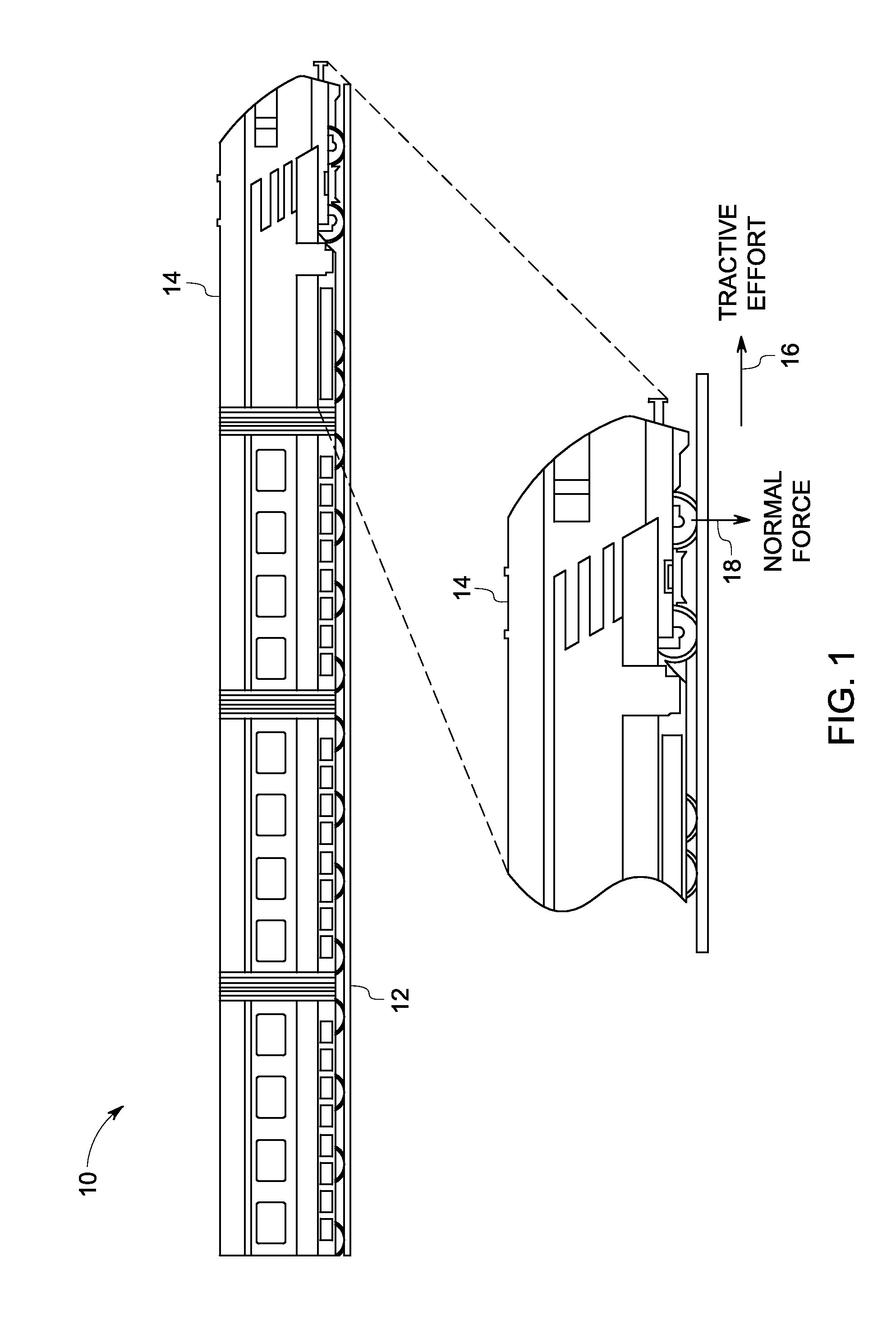
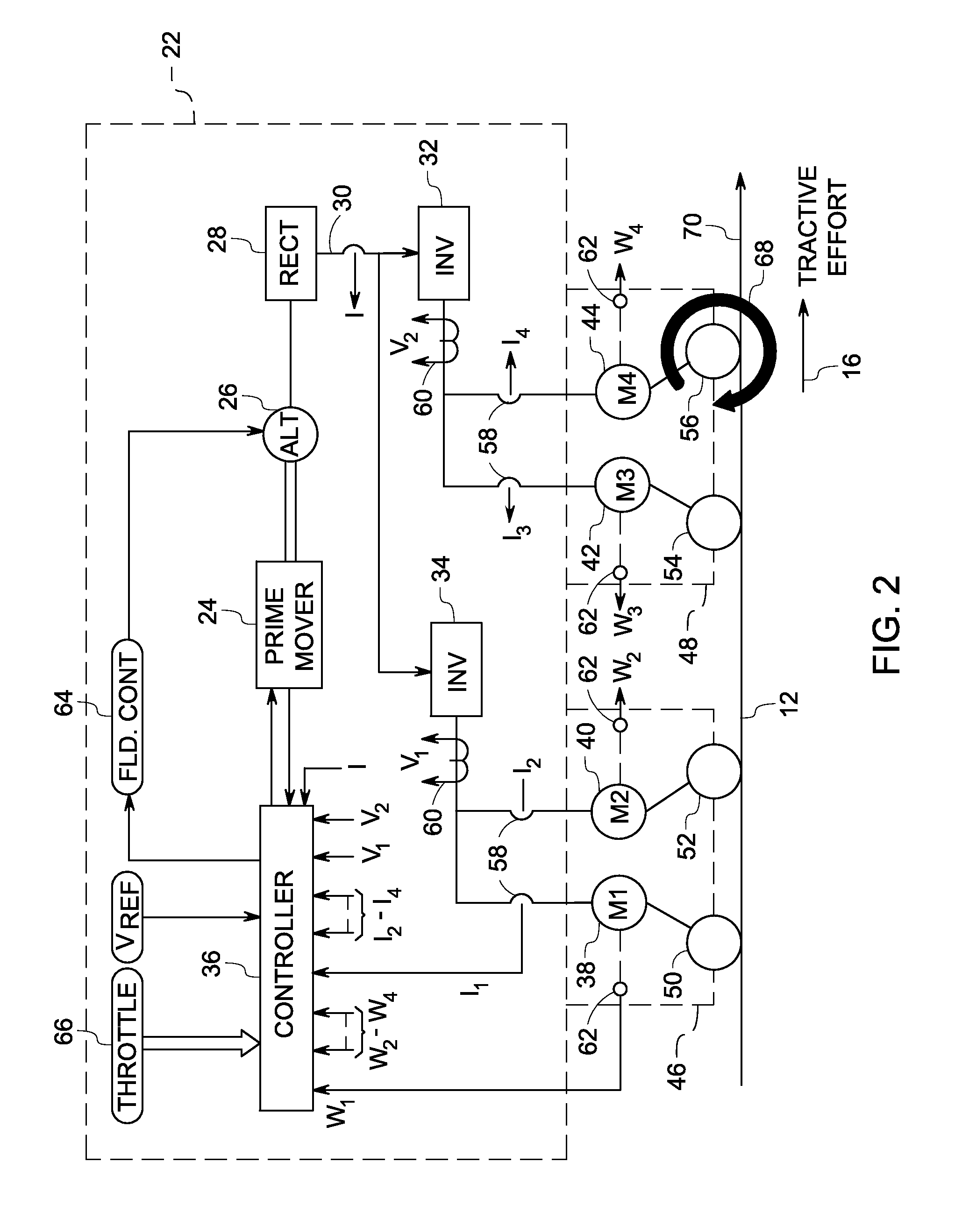
[0027]Embodiments of the inventive subject matter relate to systems and methods for traction motor control in a vehicle. Onboard the vehicle is a vehicle traction system, which includes a control system and a traction motor system. The traction motor system includes a traction motor and an inverter electrically connected to the traction motor. The control system generates signals for controlling the inverter to produce power waveforms for powering the traction motor. A wheel is operably coupled to the traction motor (e.g., through a gear and / or axle set). The wheel is driven by the motor during a motoring mode of operation, and the wheel drives the motor during a dynamic or regenerative braking mode of operation. The control system also comprises a first control module and a second control module. (The modules may comprise electronic hardware and / or software, and may be part of a common controller card or similar electronics unit for motor control.) The first control module is confi...


PUM


Abstract

A control method includes monitoring changes in torque produced by a traction motor when an excitation frequency of current supplied to the traction motor changes, determining if the torque produced by the traction motor decreases when the excitation frequency of the current supplied to the traction motor increases, and responsive to the torque produced by the traction motor decreasing when the excitation frequency increases, preventing the excitation frequency of the current supplied to the traction motor from increasing further.

Description

CROSS-REFERENCE TO RELATED APPLICATIONS[0001]This application is a continuation-in-part of U.S. application Ser. No. 13 / 632,320, filed Oct. 1, 2012, which claims priority to U.S. Provisional Application Ser. No. 61 / 542,796, filed Oct. 3, 2011, the entire disclosures of which are incorporated by reference.FIELD[0002]Embodiments of the inventive subject matter described herein relate to motor control. Other embodiments relate to traction motor control in a vehicle.BACKGROUND[0003]Certain rail vehicles (e.g., locomotives) and other off-highway vehicles are powered by electric traction motors coupled in driving relationship to one or more axles of the vehicle. In a motoring mode of operation, the traction motors are supplied with electric current from a controllable source of electric power such as an engine-driven traction alternator. The traction motors apply torque to the vehicle wheels, which in turn exert tangential force (tractive effort) on the surface on which the vehicle is tra...

Claims


Application Information

Patent Timeline
IPC IPC(8): H02P23/00B60L50/13
CPCH02P23/0063B61C15/12B60L3/102B60L3/104B60L15/2063B60L2220/46B60L2240/12B60L2240/421B60L2240/423B60L2240/429B60L2240/461B60L2240/463B60L2240/465B60L2260/28B60L2200/26H02P23/20B60L50/13Y02T10/64Y02T30/00Y02T10/7072Y02T10/72Y02T10/70
Inventor DAIGLE, JEFFREY LOUIS
Owner GE GLOBAL SOURCING LLC
Learn More