Renewable blended natural gas and rock wool production from a plasma-based system

a plasma-based system and natural gas technology, applied in the field of plasma-based plasma-based systems, can solve the problems of increasing the electricity cost of operating the plasma torch, tightening emission regulations, etc., and achieve the effects of enhancing the control of gasification products, enhancing temperature, and increasing energy

Inactive Publication Date: 2013-12-05
JURANITCH JAMES C +2
View PDF0 Cites 4 Cited by
  • Summary
  • Abstract
  • Description
  • Claims
  • Application Information

AI Technical Summary

Benefits of technology

[0016]Control over the gasification products is enhanced by providing in some embodiments an inlet for delivering lime into the gassifier chamber. Additionally, there is provided in some embodiments a natural gas inlet for delivering natural gas into the gassifier chamber. Such natural gas enhances the temperature within the gassifier chamber.
[0017]In an advantageous embodiment, the fuel injection arrangement is configured as a sleeve arranged to surround the electrically operated plasma torch. The sleeve is provided with a plurality of circum

Problems solved by technology

However, emission regulations have been tightened concurrently with an

Method used


Image

  • Renewable blended natural gas and rock wool production from a plasma-based system
  • Renewable blended natural gas and rock wool production from a plasma-based system
  • Renewable blended natural gas and rock wool production from a plasma-based system

Examples


Embodiment Construction

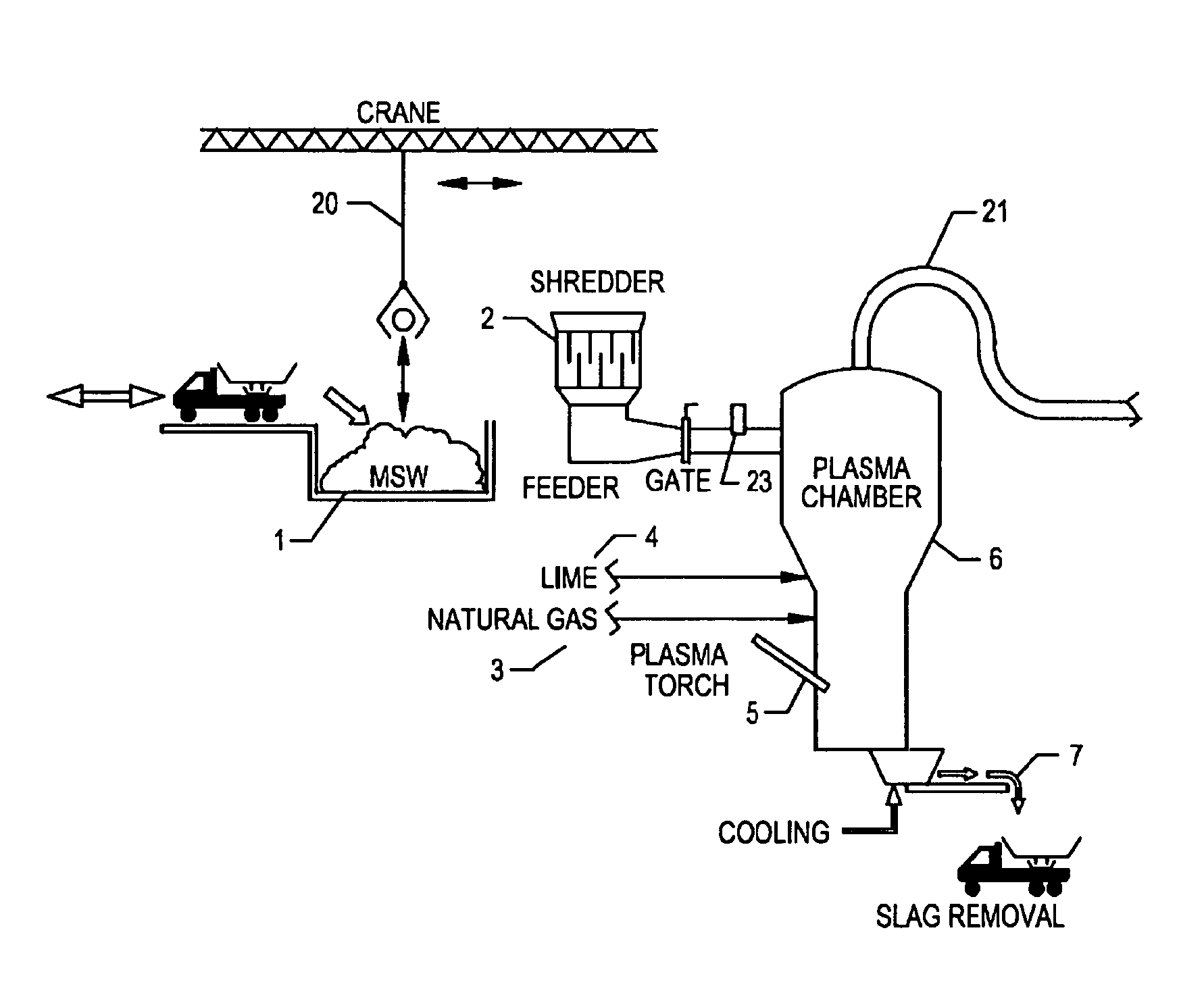
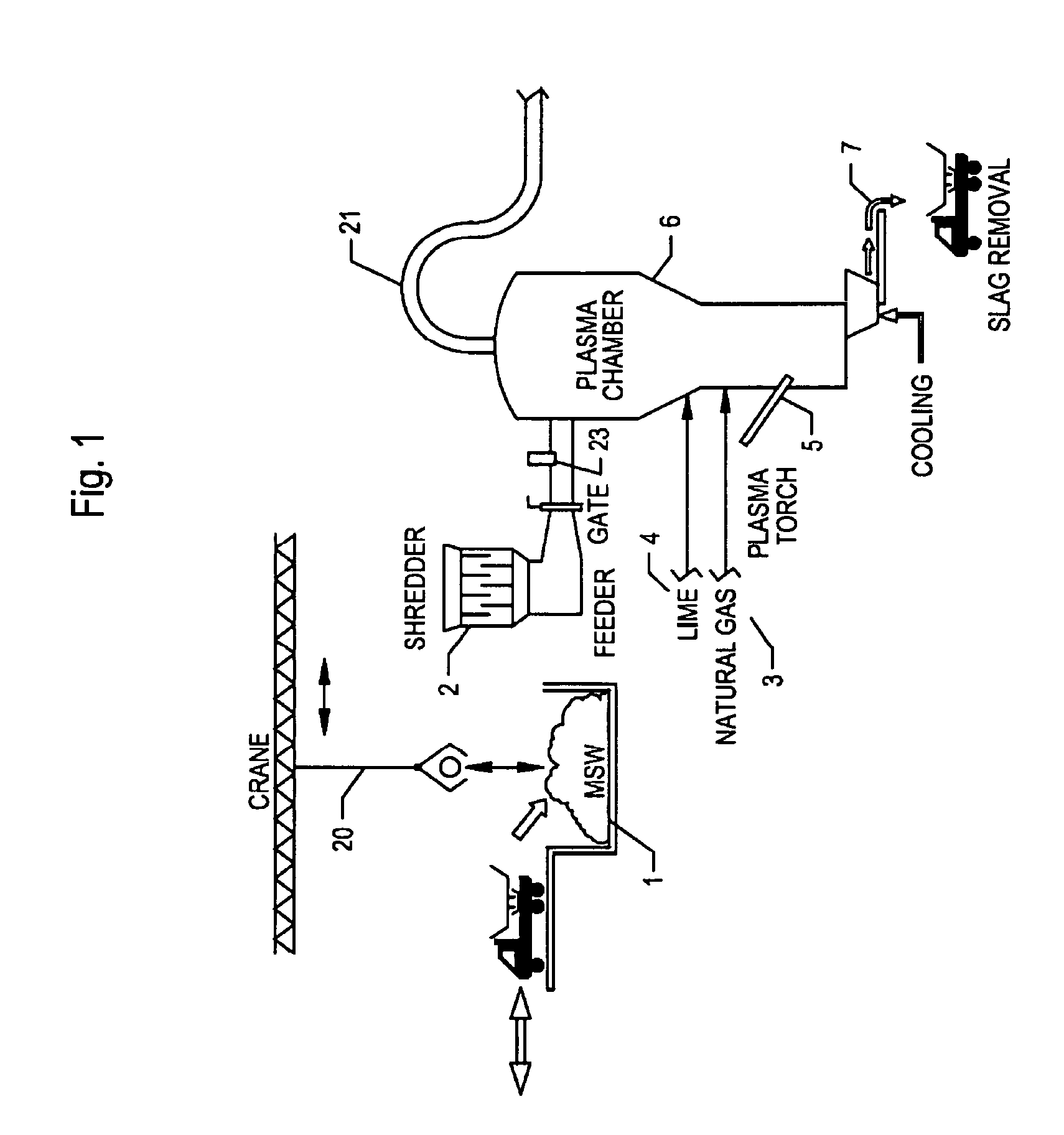
[0023]FIG. 1 is a simplified schematic representation of a process and system for a conventional plasma gassifier modified for a chemical fuel injection system constructed in accordance with the principles of the invention. As shown in this figure, MSW 1 (municipal solid waste) or other feedstock is delivered, in this specific illustrative embodiment of the invention, by a crane 20. The feedstock can be any organic material, or an inorganic mix. Crane 20 transfers MSW 1 to a shredder 2. The shredded feedstock (not shown) is then delivered to a gassifier chamber 6.

[0024]The feed system, which includes shredder 2, compresses the incoming feedstock MSW 1 so as to minimize the introduction of air. Plasma chamber 6 is advantageously operated in pyrolysis mode or in air and / or oxygen combustion boosted modes of operation. Additives such as lime 4 are added, in this embodiment, to the gassifier to control emissions and improve the quality of an output slag 7, which in this specific illustr...


PUM


Abstract

A method and system for augmenting the heat energy of a plasma torch in a gassifier using chemical energy, including the steps of injecting a fuel in the proximity of a plasma torch inside the gassifier chamber; and injecting an oxidant in the proximity of a plasma torch inside the gassifier chamber. As apparatus, an enhanced plasma gassifier arrangement is of the type that has a gassifier chamber having an electrically operated plasma torch for issuing a plasma discharge into the gassifier chamber. A fuel injection arrangement is disposed to surround the electrically operated plasma torch for injecting a fuel and an oxidant into the gassifier chamber. A natural gas inlet delivers natural gas into the gassifier chamber, thereby enhancing the temperature within the gassifier chamber.

Description

BACKGROUND OF THE INVENTION[0001]1. Field of the Invention[0002]This invention relates generally to processes and systems for augmenting the plasma heat in a plasma chamber.[0003]2. Description of the Related Art[0004]Plasma gasification continues to grow in popularity. To date the plasma heat source has been supplemented in a gassifier chamber with methods such as coke additive combined with loosely controlled air or oxygen injection to combust grossly existing syngas in the plasma chamber. However, emission regulations have been tightened concurrently with an increase in the cost of electricity needed to operate the plasma torch.[0005]It is, therefore, an object of this invention to reduce both, emission from the operation of a plasma power plant and the amount of electricity needed to operate a plasma torch.SUMMARY OF THE INVENTION[0006]The foregoing and other objects are achieved by this invention which provides, In accordance with a method aspect thereof, a method of producing ...

Claims


Application Information

Patent Timeline
IPC IPC(8): H05H1/26
CPCH05H1/26C10J3/18C10J2300/0906C10J2300/1238C10J2200/12C10J2300/0946C10J2300/0989C10J2300/0993C10J2300/0996C10J2300/1823
Inventor JURANITCH, JAMES C.JURANITCH, THOMAS R.TARRANT, RICHARD E.
Owner JURANITCH JAMES C
Why Eureka
Try Eureka