
Cryoablation balloon catheter and related method

a balloon catheter and balloon catheter technology, applied in balloon catheters, medical science, surgical instruments for cooling, etc., can solve the problems of nitrous oxide cooling system not being able to achieve temperature and cooling power, vapor lock effect, and inability to meet the desired miniature size of the probe tip, etc., to achieve the effect of reducing the siz

Active Publication Date: 2013-12-26
CRYOMEDIX
View PDF2 Cites 58 Cited by
  • Summary
  • Abstract
  • Description
  • Claims
  • Application Information

AI Technical Summary

Benefits of technology

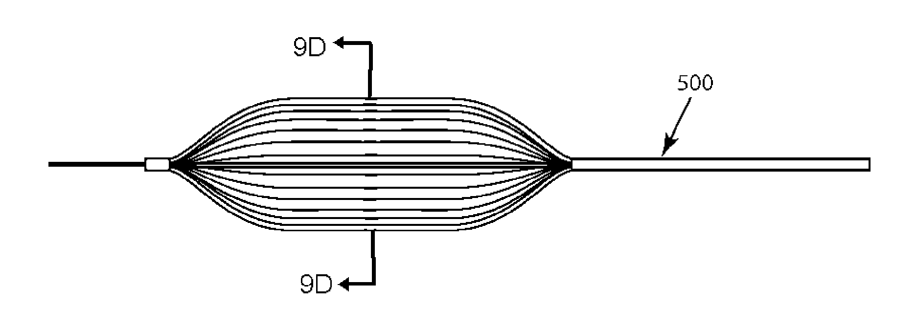
The present invention relates to a cryoablation balloon catheter for delivering energy to target tissue. The catheter includes an elongate shaft with a distal section, a cryoenergy delivering core, and a first balloon located in the distal section. The balloon is inflated with a thermally conductive liquid and the cryoenergy is delivered through the balloon to the tissue. The catheter may also include a plurality of flexible delivery tubes and at least one return tube for delivering the coolant and completing a liquid flowpath. The balloon may have multiple regions for targeted cooling, and a second balloon may surround or encase the first balloon. The invention also includes a closed loop, single phase liquid refrigerant cryoablation balloon catheter system for treating tissue.

Problems solved by technology

This enormous increase in volume results in a “vapor lock” effect when the internal space of the cryoprobe gets “clogged” by the gaseous nitrogen.
The associated heat exchanger systems within the cryoprobes are also not compatible with the desired miniature size of probe tips that need to be less than 3 mm in diameter.
Additionally, in these systems the gaseous nitrogen is simply rejected directly to the atmosphere during use which produces a cloud of condensate upon exposure to the atmospheric moisture in the operating room and requires frequent refilling or replacement of the liquid nitrogen storage tank.
The nitrous oxide cooling system is not able to achieve the temperature and cooling power provided by liquid nitrogen systems.
However, because of the insufficiently low operating temperature, combined with relatively high initial pressure, cryosurgical applications are strictly limited.
The cold returning gas also requires insulation to avoid freezing nontarget tissues along the course of the cryoprobe from the active tip segment Although an argon system is capable of achieving a desirable cryoablation temperature, argon systems do not provide sufficient cooling power and require very high gas pressures.
These limitations are very undesirable because the corresponding probe diameters are currently limited to approximately 1.5 mm OD to allow sufficient high-volume gas flow for JT cooling, which is larger than what is needed for a number of applications.
However, challenges arise from use of a near-critical cryogen in a cryoablation system.
In particular, there is still a significant density change in nitrogen (about 8 times) once it is crossing its critical point—resulting in the need for long pre-cooling times of the instrument.
The heat capacity is high only close to the critical point and the system is very inefficient at higher temperatures requiring long pre-cooling times. Additionally, the system does not warm up (or thaw) the cryoprobe efficiently.
Additionally, near-critical cryogen systems require a custom cryogenic pump which is more difficult to create and service.
However, with CO2 and N2O having respective boiling points of −78.5° C. and −88.5° C., it is doubtful that the surface temperatures of a balloon in contact with a vessel wall inside a blood vessel can reach anything lower than approximately −10° C. It is therefore uncertain, or perhaps unlikely, that any of the desired “positive remodeling” needed to keep an artery open to its balloon-dilated extent would be possible since temperatures required to get this stent-like effect need to be less than −40° C.
Therefore, it is uncertain, if not unlikely, that the above described cryo-balloons can achieve the desired temperatures within a biological system because of the physical limitations necessary for evaporative or JT-based cryosystems.
Insufficient generation of cold temperatures arise from the physical limitations of the cooling mechanisms, as well as the physical engineering limitations, proposed in the above mentioned patents.

Method used


Image

  • Cryoablation balloon catheter and related method
  • Cryoablation balloon catheter and related method
  • Cryoablation balloon catheter and related method

Examples


Embodiment Construction

[0049]Before the present invention is described in detail, it is to be understood that this invention is not limited to particular variations set forth herein as various changes or modifications may be made to the invention described and equivalents may be substituted without departing from the spirit and scope of the invention. As will be apparent to those of skill in the art upon reading this disclosure, each of the individual embodiments described and illustrated herein has discrete components and features which may be readily separated from or combined with the features of any of the other several embodiments without departing from the scope or spirit of the present invention. In addition, many modifications may be made to adapt a particular situation, material, composition of matter, process, process act(s) or step(s) to the objective(s), spirit or scope of the present invention. All such modifications are intended to be within the scope of the claims made herein.

[0050]Methods ...


PUM


Abstract

Cryoablation balloon catheters and methods are described herein. The cryoablation balloon catheter comprises a distal end section and an inflatable balloon member disposed along the distal end section for contacting a target tissue. The balloon member may be inflated with a thermally conductive liquid. One or more cooling microtubes are positioned within the balloon and a single phase liquid coolant is transported from a liquid source, through the microtubes to the distal section, and returned to a reservoir. Cryogenic energy is transferred from the microtubes, through the conductive liquid filling the balloon, through the wall of the balloon, and to the tissue. In a cryoablation balloon catheter, a plurality of flexible microtubes are adhered to a surface of the expandable balloon. Cryoenergy from the microtubes is directly transferred to the tissue.

Description

CROSS-REFERENCE TO RELATED APPLICATIONS[0001]The present application claims the benefit of provisional patent application No. 61 / 377,190 filed Aug. 26, 2010, entitled “An Improved Cryoablation Balloon Catheter with Single Phase Liquid Coolants for Intravascular Applications”.BACKGROUND OF THE INVENTION[0002]This invention relates to cryoablation systems for treating biological tissues, and more particularly, to cryoablation balloon catheters using refrigerants in the liquid state.[0003]Cryoablation therapy involves application of extremely low temperature and complex cooling systems to suitably freeze the target biological tissues to be treated. Many of these systems use cryoprobes or catheters with a particular shape and size designed to contact a selected portion of the tissue without undesirably affecting any adjacent healthy tissue or organ. Extreme freezing is produced with some types of refrigerants that are introduced through the distal end of the cryoprobe. This part of the ...

Claims


Application Information

Patent Timeline
IPC IPC(8): A61B18/02A61F2/958
CPCA61B18/02A61B2018/0022A61B2018/0212A61B2018/0262A61M2025/1086A61M2025/1093
Inventor BABKIN, ALEXEILITTRUP, PETERNYDAM, BARRONNYDAM, WILLIAM
Owner CRYOMEDIX
Learn More