Energy-saving electronic touch switch

a touch switch and electronic technology, applied in the direction of electronic switching, substation/switching arrangement details, pulse technique, etc., can solve the problems of low power consumption, quality and service life of switches, and existing popular electronic touch switches that can only be used for controlling

Active Publication Date: 2014-01-02
SHENZHEN ADA ELECTRONICS
View PDF1 Cites 20 Cited by
  • Summary
  • Abstract
  • Description
  • Claims
  • Application Information

AI Technical Summary

Benefits of technology

[0003]Aiming at the defect of the touch switch in the prior art which is not safe enough abovementioned, the present invention provides a novel energy-saving electronic touch switch, which employs capacitance touch as a touch single, and stops a user from an opportunity of contacting high voltage, so that the user is safer.
[0021]The energy-saving electronic touch switch has the beneficial effects that: the energy-saving electronic touch switch can drive various loads and has a wider range of possible loads including inductive, capacitive or purely resistive loads and high-frequency switch power source loads, such as energy-saving lights, AC (Alternating Current) motors, LEDs (Light Emitting Diodes) new light sources, common fluorescent lamps, and the like. The energy-saving electronic touch switch overcomes the disadvantages of small load range and weak load capacity of conventional switches. The energy-saving electronic touch switch is provided with a load detecting module used for detecting load voltages, and the like, and has achieved over-voltage and over-load protection. Meanwhile, the energy-saving electronic touch switch employs a switch power supply as a power supply module, which can lighten self power consumption by utilizing the high efficiency of the power supply module so as to drive loads of lower power such as an LED (Light Emitting Diode) lamp, etc. In addition, the energy-saving electronic touch switch employs chips with low power consumption such as LDO (Low Dropout Regulator) voltage regulator chips, touch chips, and the like., which can reduce the overall power consumption, wherein the overall power consumption is less than 2.2 mW (measured without a backlight indicator lamp) and the single static overall power consumption is less than 10 mW (measured under an indicator lamp). The energy-saving electronic touch switch simplifies circuits and improves the power supply utilization rate. The energy-saving electronic touch switch employs two LDOs (Low Dropout Regulators) of different voltage stabilizing values (U2=3.0V, U3=3.3V); a feeder power supply and a switch power supply separately feed power; when single LDO is switched on, the power consumption of the rest loads cannot be influenced; in this way, the energy-saving electronic touch switch really satisfies the demand of supplying power independently through self switching on and feeder. The energy-saving electronic touch switch employs different filter circuits separately for feeder low frequency filter and high frequency switch power supplies, thus eliminating the influences of resetting time while being energized; in this way, the circuits are more stable and safer. A load detecting circuit is also arranged in the energy-saving electronic touch switch to provide load detection for the switch; if the energy-saving electronic touch switch has no loads, a background indicator lamp of this circuit is not light and touch does not work; meanwhile, whether the load of this circuit is damaged (open circuit) can be judged. In case of no loads, a touch position can be judged accurately to make the energy-saving electronic touch switch more humanized. The energy-saving electronic touch switch simplifies circuits and improves the power source utilization rate. The energy-saving electronic touch switch employs different filter circuits separately for feeder low frequency filter and high frequency switch power supplies, thus eliminating the influences of resetting time while being energized; in this way, the circuits are more stable and safer.
[0022]The energy-saving electronic touch switch employs sealed explosion-proof relays as switch elements which can reach a load power of 1000 W and can satisfy the requirement of using on a switch occasion with larger power. The energy-saving electronic touch switch uses field-effect tubes to feed power and utilizes the voltage driving characteristic and internally arranged backward diodes of the field-effect tubes to switch on for a long period of term and switch off intermittently to obtain a pulsating direct current which is stabilized by a voltage stabilizing system then to feed power required, and can drive various loads.
[0024]The energy-saving electronic touch switch can implement to control same load at two places; the energy-saving electronic touch switch employs a capacitive electronic touch switch, which can achieve the functions same to the mechanical switches; the energy-saving electronic touch switch is safer and has a longer service life; meanwhile, the problem of service life of the mechanical switch can be stopped. The energy-saving electronic touch switch has ultra-low power consumption; under a standby state, the combined power consumption of two groups of switches is approximately 20 mW, which is far lower than the standby power consumption specified by energy standards; moreover, the energy-saving electronic touch switch employs a single wire mechanism, which can replace the mechanical switch directly without needing to rewire, thus saving wires and labor cost. The energy-saving electronic touch switch is suitable for controlling the same load (such as lamp, motor, fan, etc) at two places; for example, while installing the energy-saving electronic touch switch on a corridor, the energy-saving electronic touch switch can be touched to turn on a stair lamp on the first floor and can be touched at the other end to turn off after arriving at the second floor. In view of home use, multiple energy-saving electronic touch switches can be installed at the entrance of the house; after corresponding lamps are turned on, the lamps can be turned off by using the energy-saving electronic touch switches of this type at each subcontrol point, thus stopping returning to the entrance of the house to turn off the lamp and then returning to the place that the lamp is lighting in the dark.

Problems solved by technology

At present, most alternating current switches in the market are mechanical type key switches which needs to be pulled manually so as to implement switching on and off of a control circuit; the mechanical type key switches have many inconveniences on operation; moreover, the quality and service lives of the switches cannot be guaranteed; meanwhile, the mechanical type key switches also have problems such as mechanical wear and sparks occurred during switching on and off, and the like, and are not applicable to certain occasions such as inflammable, explosive and coal gas leaking rooms, etc.
However, the existing popular electronic touch switches can only be used for controlling filament lamps usually due to high power consumption thereof.
Moreover, the existing popular electronic touch switches cannot control inductance type fluorescent lamps, low power consumption (usually the power is less than 5 W) LED (Light Emitting Diode) lamps and inductance type loads thereof (such as a low power consumption motor).
Meanwhile, multi-circuit control cannot be implemented on one switch box of the existing electronic switch; moreover, the touch method of the existing electronic switch is metal contact which is lack of sense of safety.
All the touch switches in the prior art only have single-point on-off control function, which has many inconveniences on application.
The electronic switches at present do not have the output detection function generally, are easy to cause danger while outputting over-voltage and over-load, and have hidden safety troubles.

Method used


Image

  • Energy-saving electronic touch switch
  • Energy-saving electronic touch switch
  • Energy-saving electronic touch switch

Examples


first example embodiment (as illustrated in fig.2 to fig.6)

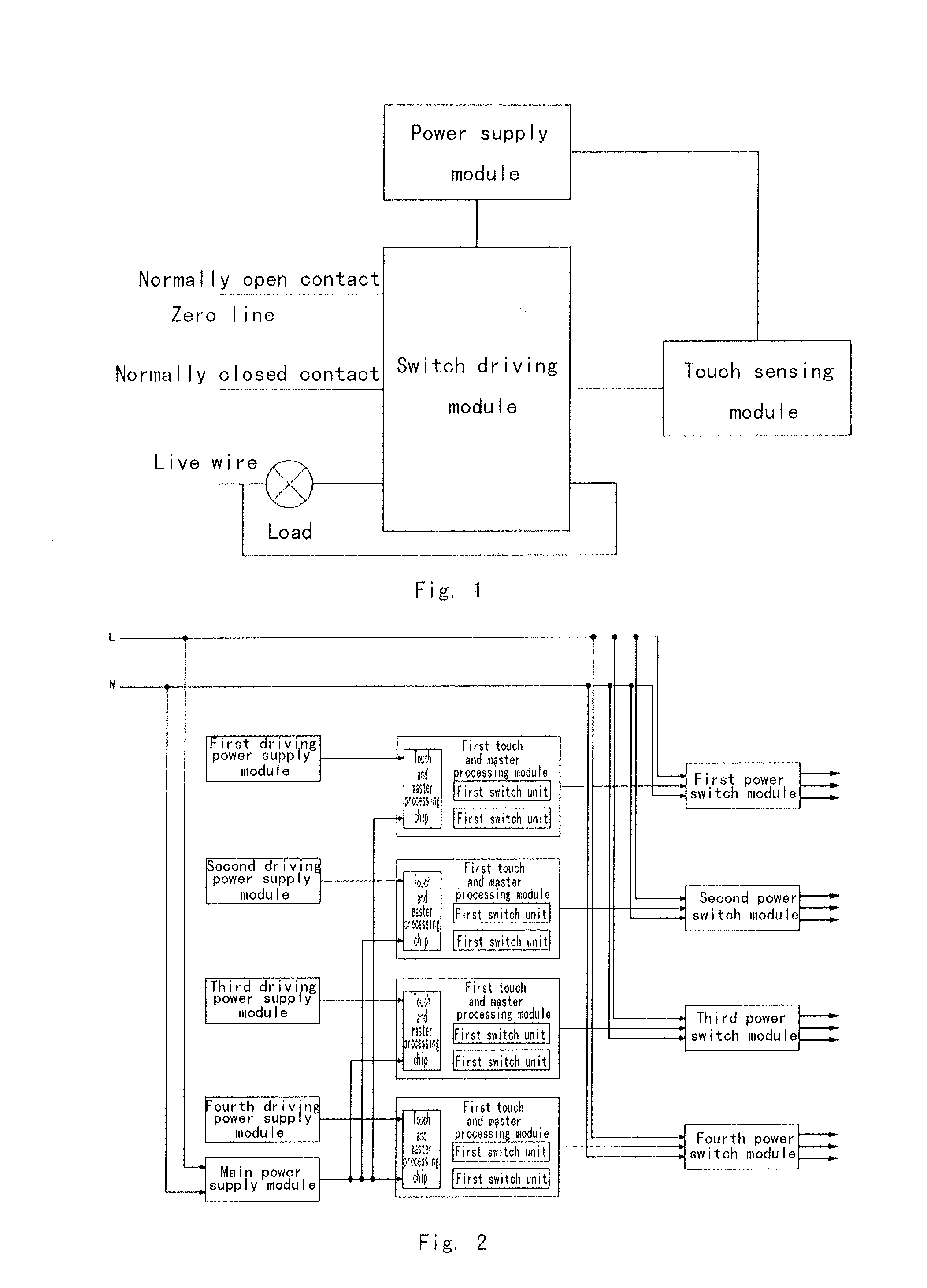
[0044]First example embodiment (as illustrated in FIG. 2 to FIG. 6): as illustrated in FIG. 2, the example embodiment mainly comprises a capacitive touch switch, a touch sensing module, a driving power supply module, a power switch module and a main power supply module; both the driving power supply module and the main power supply module in the example embodiment belong to the power supply module; the capacitive touch switch is connected onto the touch sensing module; an on-off signal is inputted to the touch sensing module through the capacitive touch switch, the capacitive touch switch controls the power switch module to work, the power switch module supplies power to loads, the main power supply module provides electric energies to the power switch module, and the driving power supply module supplies power to other modules.

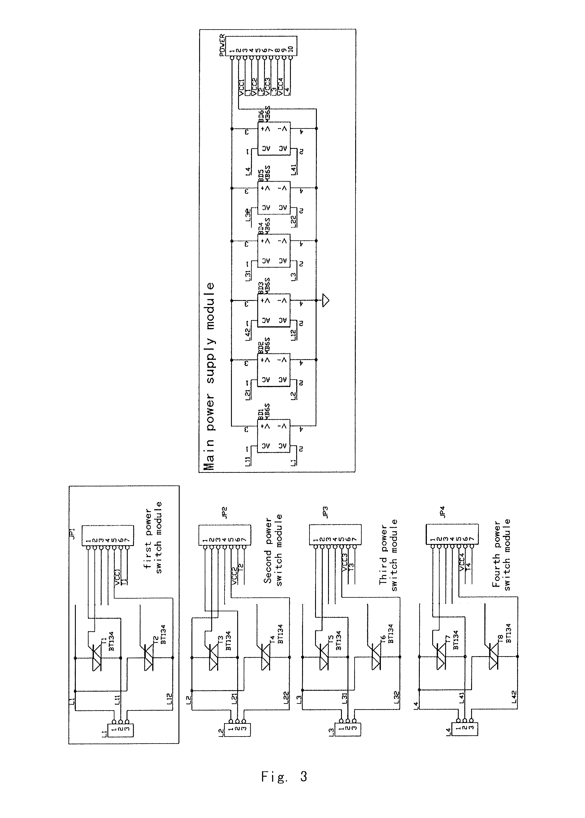
[0045]In the example embodiment, the structure of the example embodiment is described concretely by taking that four channels are arranged in the same switch ...

second example embodiment

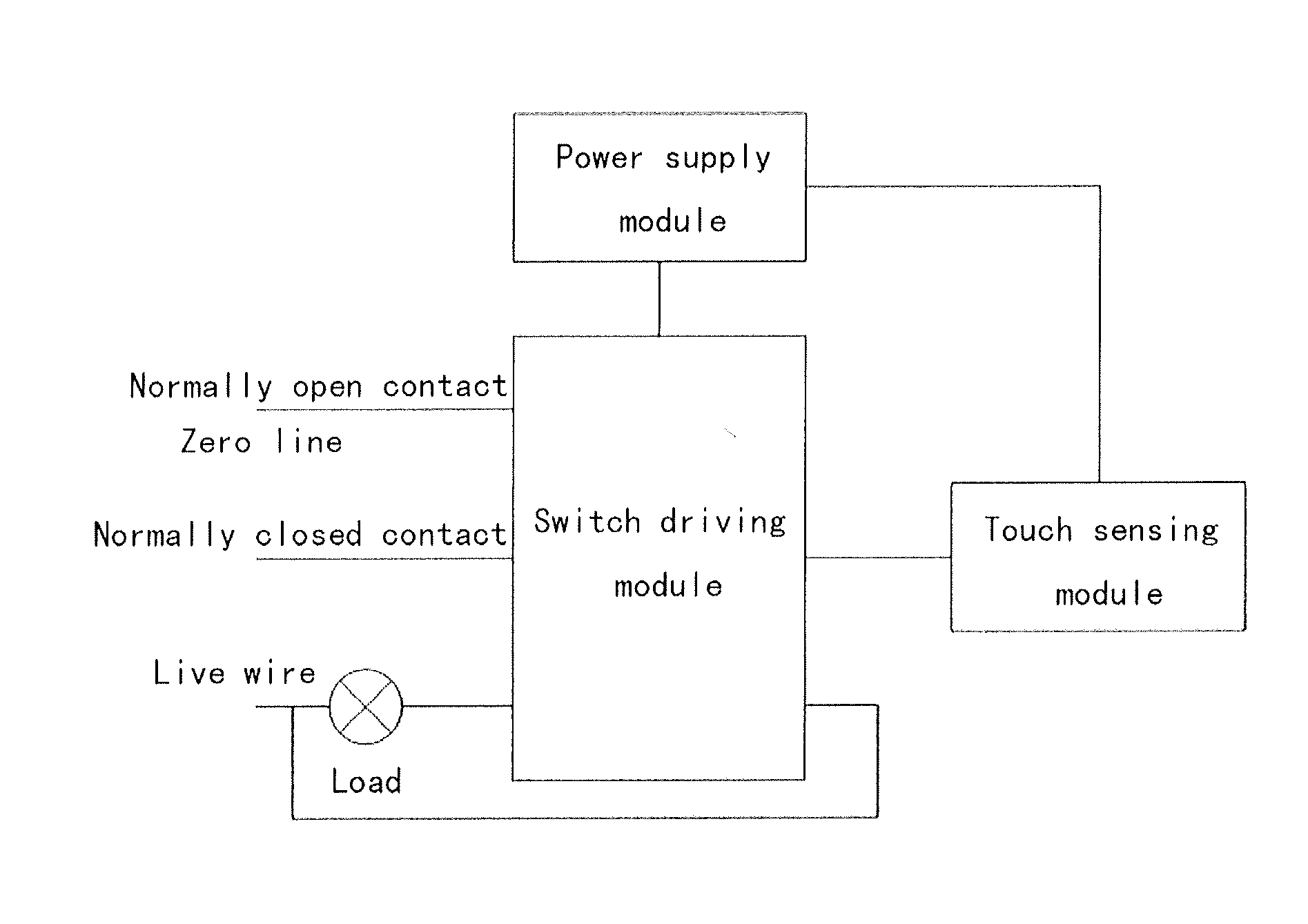
[0049] as illustrated in FIG. 7, the example embodiment mainly comprises a touch sensing module, a power supply module and a switch driving module, wherein the touch sensing module is used for receiving a touch sensing signal inputted by a capacitive touch switch, and controlling the action of the switch driving module according to the touch sensing signal, so as to switch on a power supply circuit for the load; and the power supply module feeds power to the touch sensing module.

[0050]As illustrated in FIG. 7 and FIG. 12, a core device of the touch sensing module in the example embodiment is a touch sensing chip U6; in the example embodiment, a touch sensing chip with a model of ADPT005 is employed as the touch sensing chip U6, which comprises five touch sensing inputs and five I / O (Input / Output) ports and has data processing capacity; the touch sensing chip U6 is a low power consumption touch device, the static power consumption of which is less than 5 uA; during concrete implement...

third example embodiment

[0053] as illustrated in FIG. 8, the example embodiment mainly comprises a touch sensing module, a power supply module, a switch driving module and a load detecting module, wherein the touch sensing module is used for receiving a touch sensing signal inputted by a capacitive touch switch, and controlling the action of the switch driving module according to the touch sensing signal, so as to switch on a power supply circuit for the load; the power supply module feeds power to the touch sensing module; and the load detecting module detects the voltage outputted by the switch driving module and feeds back to the touch sensing module.

[0054]As illustrated in FIG. 8 and FIG. 13, a core device of the touch sensing module in the example embodiment is a touch sensing chip U4; in the example embodiment, a touch sensing chip with a model of ADPT008 is employed as the touch sensing chip U4, which comprises eight circuit touch sensing inputs and eight I / O (Input / Output) ports and has data proces...


PUM


Abstract

The present invention discloses an energy-saving electronic touch switch, comprising a touch sensing module, a power supply module and a switch driving module, wherein the touch sensing module is used for receiving a touch sensing signal inputted by a capacitive touch switch, and controlling the action of the switch driving module according to the touch sensing signal, so as to switch on a power supply circuit for the load; and the power supply module feeds power to the touch sensing module. The touch switch can drive various loads and has a wider range of possible loads including inductive, capacitive or purely resistive loads and high-frequency switch power supply loads, such as energy-saving lights, AC (Alternating Current) motors, LEDs (Light Emitting Diodes) new light sources, common fluorescent lamps, and the like. The energy-saving electronic touch switch overcomes the disadvantages of small load range and weak load capacity of conventional switches. The energy-saving electronic touch switch employs chips with low power consumption such as LDO (Low Dropout Regulator) voltage regulator chips, touch chips, and the like., which can reduce the overall power consumption, wherein the overall power consumption is less than 2.2 mW and the single static overall power consumption is less than 10 mW (measured under an indicator lamp). The energy-saving electronic touch switch simplifies circuits and improves the power supply utilization rate.

Description

FIELD OF THE INVENTION[0001]The present invention discloses a touch switch, and in particular, to an energy-saving electronic touch switch.BACKGROUND OF THE RELATED ART[0002]At present, most alternating current switches in the market are mechanical type key switches which needs to be pulled manually so as to implement switching on and off of a control circuit; the mechanical type key switches have many inconveniences on operation; moreover, the quality and service lives of the switches cannot be guaranteed; meanwhile, the mechanical type key switches also have problems such as mechanical wear and sparks occurred during switching on and off, and the like, and are not applicable to certain occasions such as inflammable, explosive and coal gas leaking rooms, etc. In this case, electronic type switches such as touch switches, voice operated switches and vibroswitchs which do not cause dangerous situations such as sparks during the on and off process are produced. However, the existing p...

Claims


Application Information

Patent Timeline
Patent Type & Authority Applications(United States)
IPC IPC(8): H03K17/96
CPCH03K17/962H03K17/725H03K17/7955
Inventor XIAO, XINGCHAOLIN, QINGGUANGYAN, CAIHONG
Owner SHENZHEN ADA ELECTRONICS
Why Eureka
Try Eureka