

Apparatus and method for electronic brachytherapy
a technology of electronic brachytherapy and apparatus, applied in the field of system, apparatus, method and computer program product for brachytherapy guidance, can solve the problems of real-time ultrasonic imaging, severely limit the placement accuracy, and disadvantageous radiation exposure of patients, so as to facilitate radiation therapy, improve the accuracy of position and movement information, and reduce the deviation of dosimetry
- Summary
- Abstract
- Description
- Claims
- Application Information
AI Technical Summary
Benefits of technology
Problems solved by technology
Method used
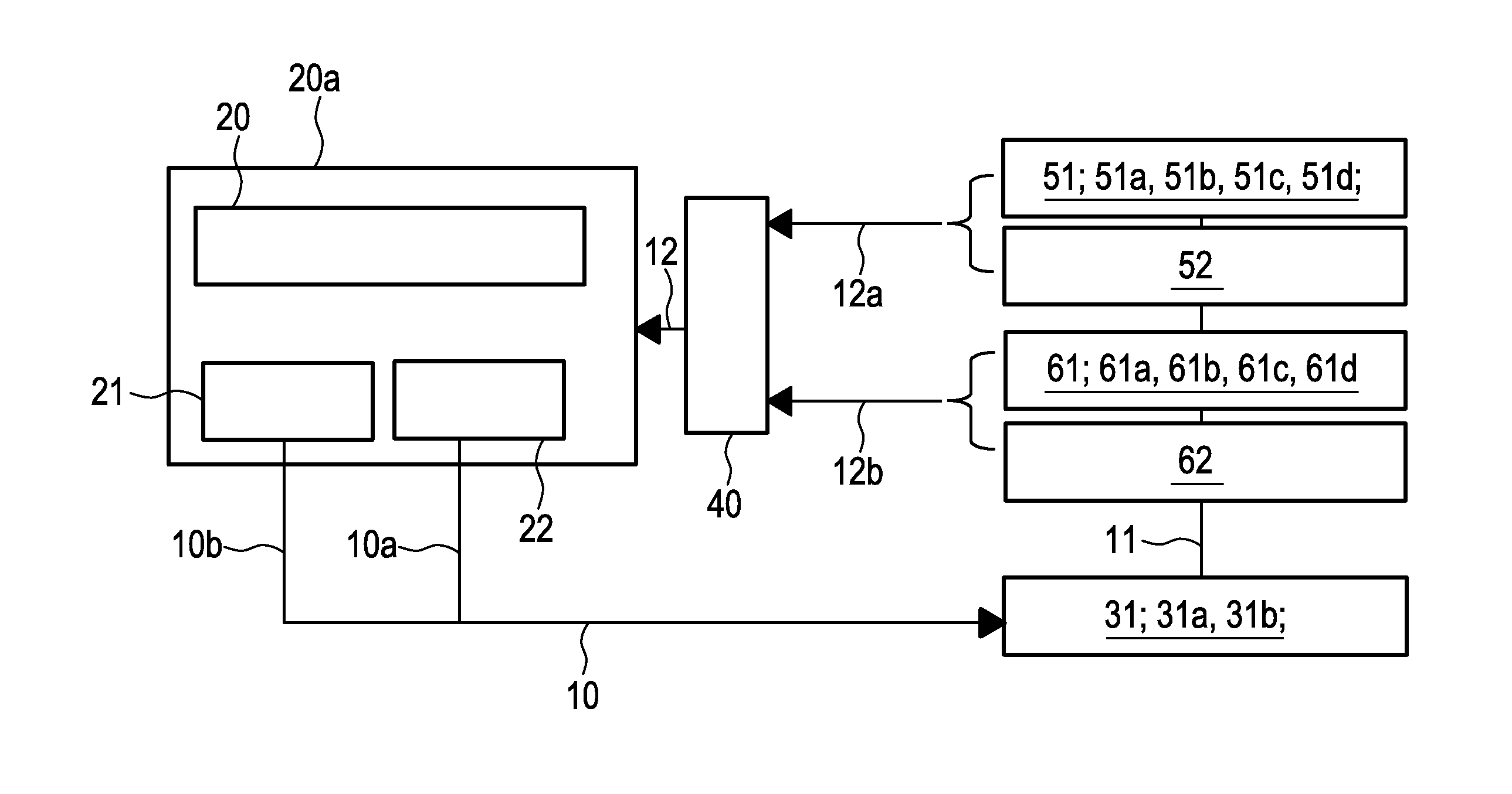
Image

Examples
first embodiment
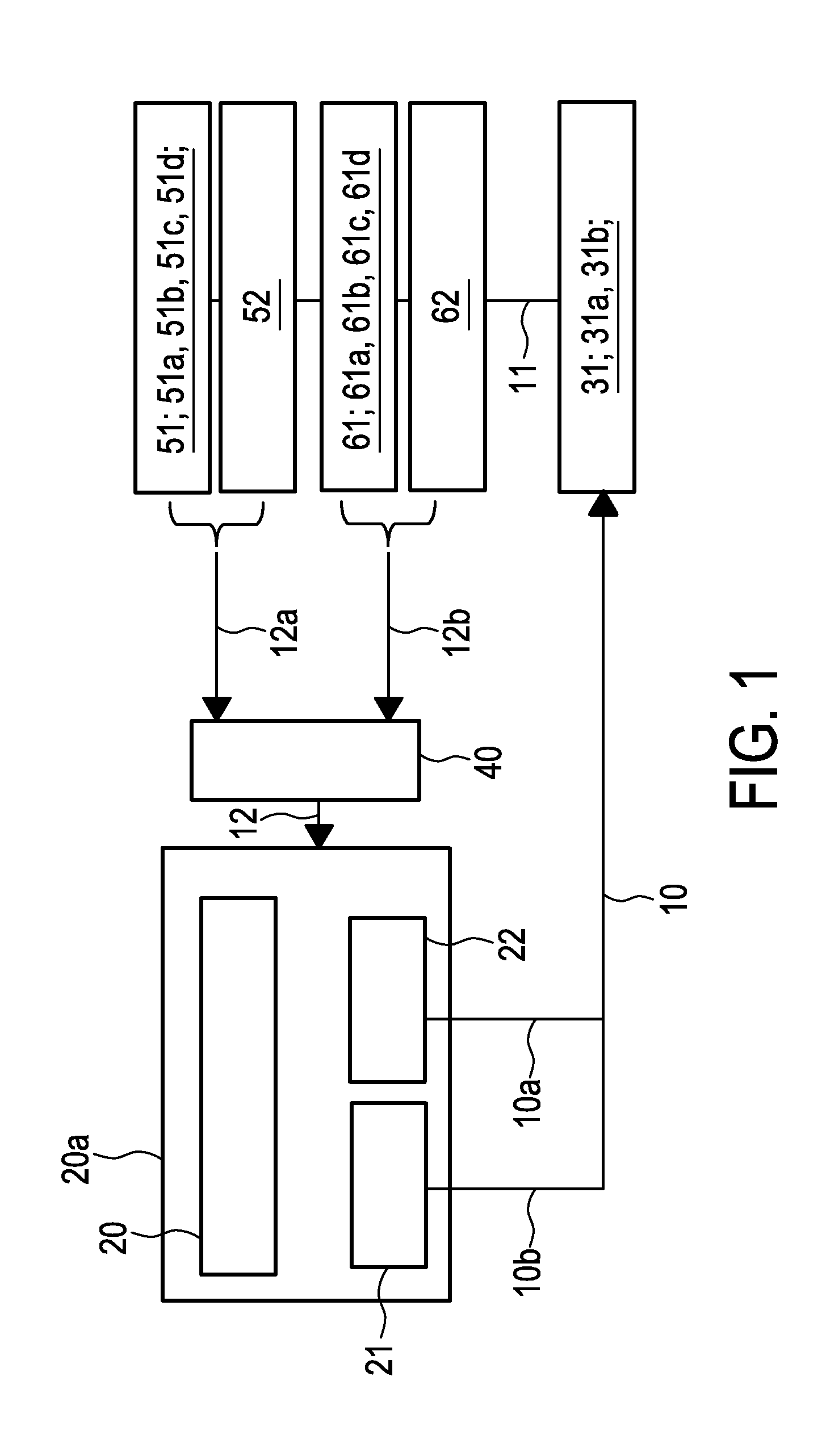
[0041]FIG. 2 shows a schematic drawing of a brachytherapy applicator 30 incorporating two means for localization. Thereby, an applicator device can be provided in the form of at least one catheter resp. catheter-like device and / or in the form of an applicator. The radiation source 31 is placed at a distal end 30a of the applicator 30, especially within radiation source guiding means 33. The means for localization are both provided in position sensor guiding means 34 adjacent to radiation source guiding means 33. In particular, a first position sensor 61 is provided in the form of a fiber 61a, e.g. a FBG fiber, extending along the position sensor guiding means 34, and a second position sensor 62 is provided in the form of an EM coil at the distal end 30a of the applicator 30, wherein in this embodiment, a second EM coil is provided around the first position sensor 61, especially within the applicator 30 and at a distance to the distal end 30a of about ⅓ of the absolute length of the...
second embodiment
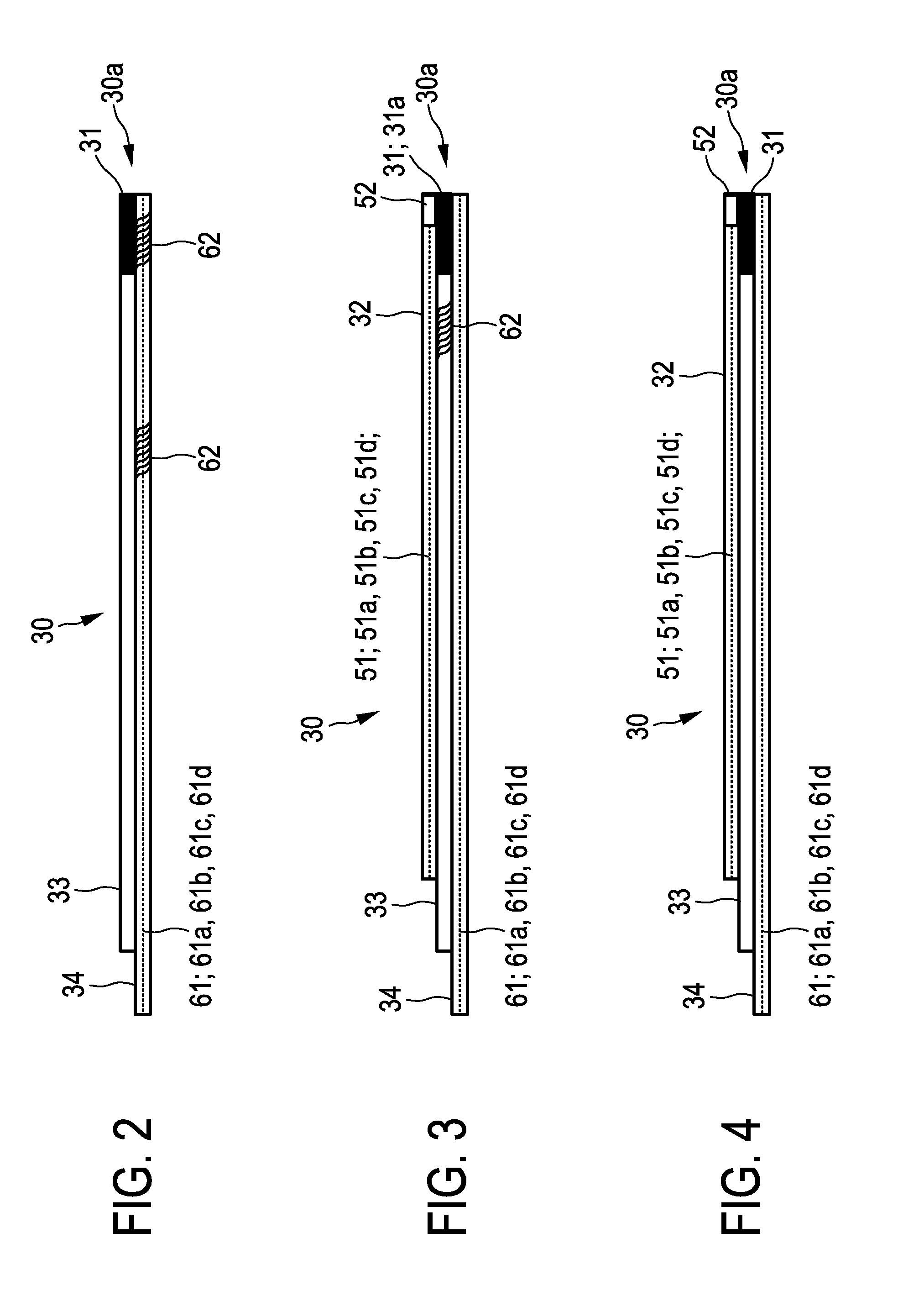
[0042]FIG. 3 shows a schematic drawing of an applicator 30 incorporating two means for localization as well as means for monitoring. The radiation source 31 is placed as shown in FIG. 1. The means for localization are provided in the position sensor guiding means 34 as well as in the radiation source guiding means 33. In particular, the first position sensor 61 is provided in the position sensor guiding means 34, and a second position sensor 62 is provided in the radiation source guiding means 33, especially behind the radiation source 31. Further, the applicator 30 comprises tissue sensor guiding means 32 provided for housing at least one of a first and second tissue sensors 51, 52. In particular, the first and / or second tissue sensor 51, 52 can be arranged at or at least proximate to a distal end 30a of the applicator 30. Thereby, a first tissue sensor 51 can be provided in the form of a pH sensor 51a. Alternatively, the first tissue sensor 51 can be provided in the form of an O2...
third embodiment
[0044]FIG. 4 shows a schematic drawing of an applicator incorporating means for localization as well as two means for monitoring. The radiation source 31 is placed as shown in FIGS. 1 and 2, that is to say, within radiation source guiding means 33. The means for localization are provided in the form of the first position sensor 61 in the position sensor guiding means 34. Further, the applicator 30 comprises tissue sensor guiding means 32 provided for housing a first and a second tissue sensors 51, 52. Thereby, as mentioned in context with FIG. 3, the first tissue sensor 51 can be provided in the form of a pH sensor 51a or an O2 sensor 51b, an optical spectroscopy sensor 51c or an optical coherence tomography sensor 51d. The second tissue sensor 52 is provided in the form of an ultrasonic probe 52, both sensors 51, 52 being arranged within tissue sensor guiding means 32. It shall be understood that tissue sensors 51, 52 alternatively can be arranged within position sensor guiding me...
PUM
 Abstract
Description
Claims
Application Information