
Drug-eluting polymer coated implantable electrode

a technology of drug-eluting polymer and implantable electrodes, which is applied in the direction of electrotherapy, connection, therapy, etc., can solve the problems of difficult coating uniformity, high cost of coating testing, and difficult coating process

Active Publication Date: 2014-01-02
MEDTRONIC INC
View PDF2 Cites 12 Cited by
  • Summary
  • Abstract
  • Description
  • Claims
  • Application Information

AI Technical Summary

Benefits of technology

The present patent describes implantable electrodes, leads, and methods for coating electrodes with a drug in a polymer matrix. The polymer matrix is biocompatible and does not significantly interfere with, and may enhance, desired electrical characteristics or functioning of the electrode during use. The patent also describes a specific composition of a polymer called BIOCOMPATIBLE CONTROLLED RELEASE COATINGS FOR MEDICAL DEVICES AND RELATED METHODS. The coating of the electrode with this composition does not substantially adversely affect impedance properties of the electrode. The devices, systems, and methods described in this patent provide advantages over prior devices, systems, and methods.

Problems solved by technology

Without polymer binder, the coating process can be challenging.
For example, coating uniformity can be difficult to achieve.
In addition, testing of the coating in these cases can be costly because testing must occur on an entire lead.
Accordingly, if coating of the electrode does not meet manufacturing specifications, the entire lead is scrapped.
However, because coatings of drugs applied directly to electrodes are not typically very durable, such direct coating is often not possible earlier in the manufacturing process.
However, many polymers are electrically insulating and thus would be functionally incompatible for coating of an electrode.
Further, the biocompatibility of many electrically conductive polymers is not yet known.
Selection of a polymer for coating of an electrode that is biocompatible and that does not significantly interfere with the electrical properties of the electrodes can be challenging.
However, U.S. Pat. No. 8,088,404 does not disclose whether such polymers have suitable electrical properties for coating electrodes of such leads, and the chemical nature of suggests that they may be electrically insulating.

Method used


Image

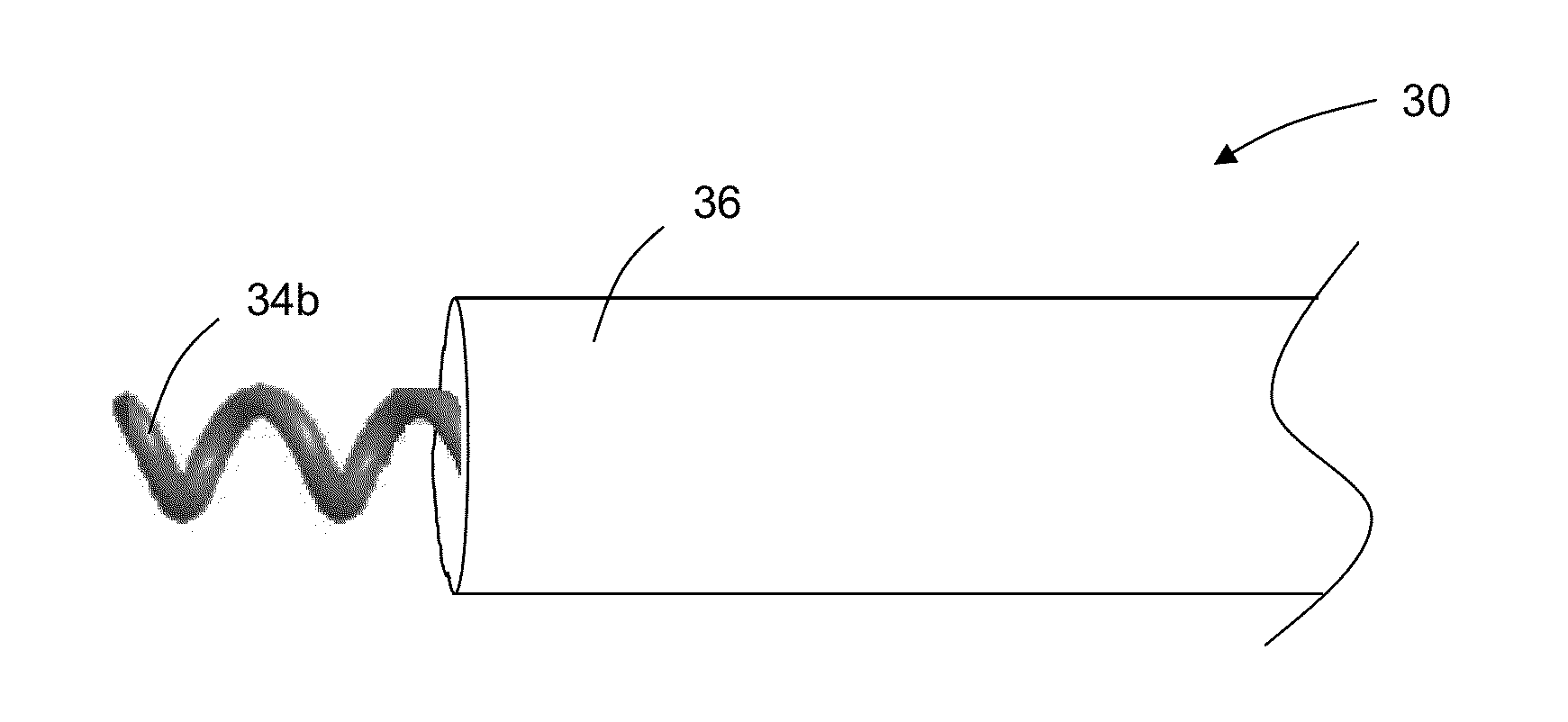
  • Drug-eluting polymer coated implantable electrode
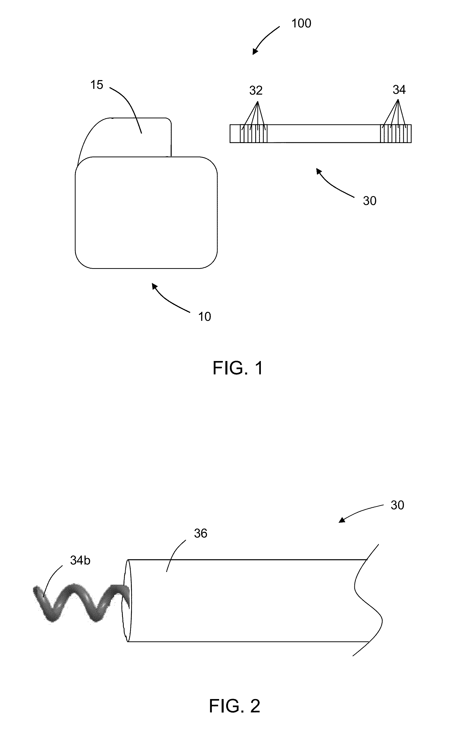
  • Drug-eluting polymer coated implantable electrode
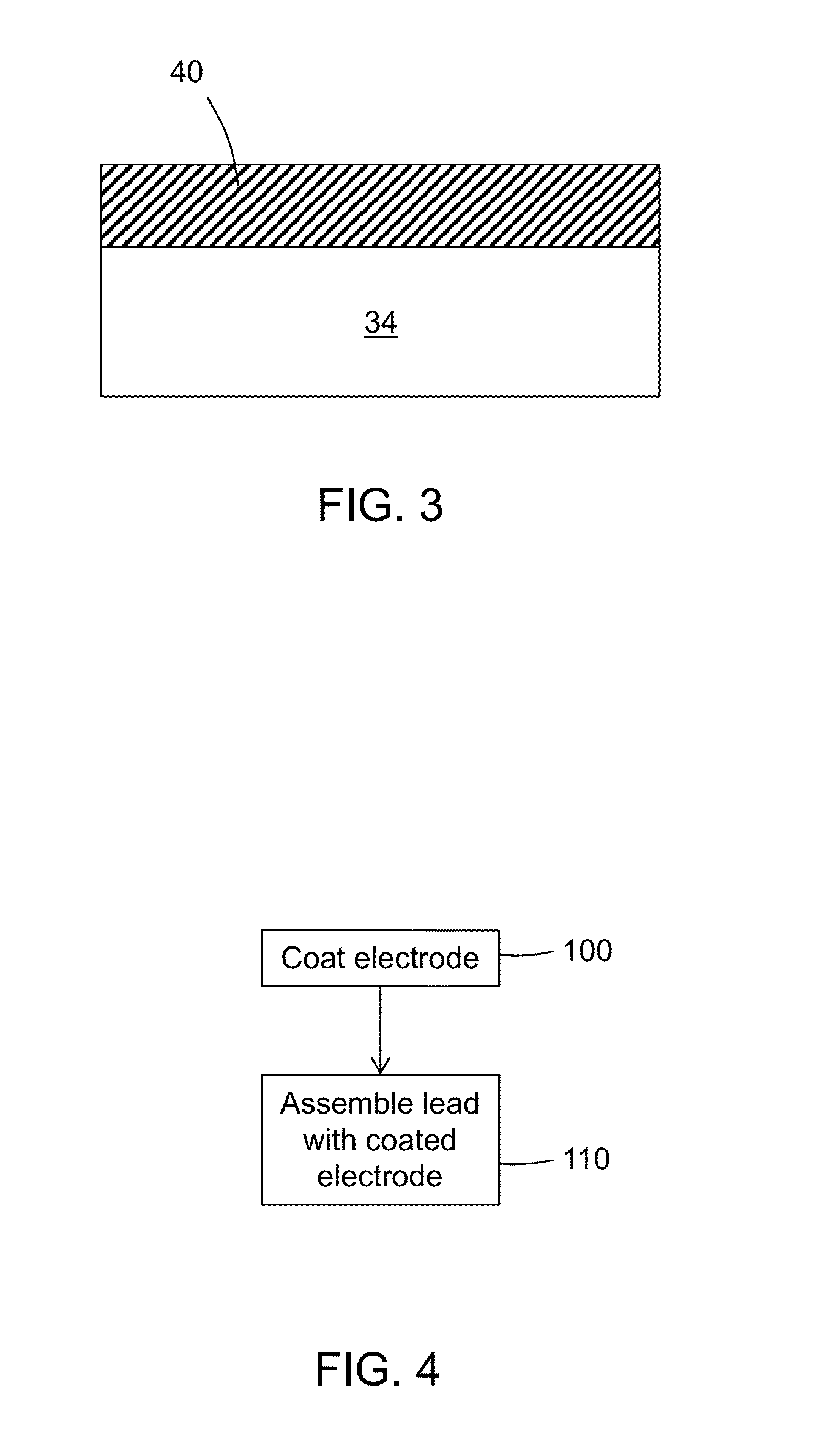
  • Drug-eluting polymer coated implantable electrode

Examples


example 1

Coating Composition and Process

[0079]Titanium Nitride helix tip electrodes of Medtronic, Inc.'s SELECT-SECURE Model 3830 leads were coated as follows.

[0080]For BDP alone, BDP was dissolved in isopropyl alcohol to generate a saturated BDP solution. The saturated BDP solution was applied to the helix tip electrode of an assembled Model 3830 lead, and the isopropyl alcohol was allowed to evaporate. Alternatively, an approximate 0.2% BDP solution was prepared in acetone. The solution was then transferred to a syringe. Using Electro-Nano-Spray (ENS) process, the solution was forced into a nozzle and under pressure accelerated into an electrical field. In this electrical field, the solution was dispersed into droplets due to the their repulsive charges and the charges droplets were deposited on to the target (helix electrode).

[0081]For BDP-PTMC, a 20% BDP / 80% PTMC composition was prepared as follows. Briefly, appropriate amounts of BDP and PTMC were dissolved in solvent (DCM / IPA=3:1 ratio...

example 2

Elution Profile

[0087]Elution of BDP from electrodes coated as described in Example 1 above was evaluated as follows. Briefly, the coated electrodes were placed in a solution of phosphate buffered saline (PBS) with 5% sodium dodecyl sulfate (SDS), pH 7, at 37° C. for two weeks. At two, four, eight, 13, 48, 72, 169 and 336 hours after incubation of the coated electrode in the PBS / SDS, a 10 microliter aliquot was sampled and evaluated for BDP by using high performance liquid chromatography (HPLC) procedures. The elution profiles are depicted in FIG. 5 for electrodes coated with BDP-PLGA, BDP-PTMS and BDP-Biolinx® in terms of cumulative percent of BDP eluted over time.

[0088]As an alternative, electrodes coated with BDP-alone, BDP-PLGA, BDP-PTMC, or BDP-Biolinx® were placed in a 50 / 50 (v / v) methanol / water solution at room temperature for one week. At 0.24, 2, 4, 8, 24, 48, 96, and 168 hours aliquots were sampled and evaluated for BDP as described above. Elution profiles are depicted in F...

example 3

Electrical Properties

[0094]Electrical impedance as a function of time in saline solution and the impedance-frequency scans of coated helix tip electrodes of Medtronic Model 3830 leads, which tip electrodes were coated as described above in Example 1, were tested in vitro. Briefly, the unipolar impedance of the coated electrode was measured between the coated electrode and the indifferent electrode in a salt solution tank at controlled temperature. The measurement was taken at the initial soak point and after approximately one, four and 24 hours. The impedance-frequency scans were carried over the frequency ranges from 0.1 Hz to 10,000 Hz in the saline solution tank.

[0095]Results are presented in FIGS. 7-8. In FIG. 7, the resistance relative to soak time is displayed. In FIG. 8, impedance vs. frequency is shown.

[0096]As shown in FIGS. 7-8, the leads having the distal tip helix electrode coated with BDP-alone, either by dip coating or ENS coating, produced similar impedance values, wh...


PUM

PropertyMeasurementUnit
weight percentaaaaaaaaaa

Abstract

An electrode of an implantable medical lead is coated with a polymeric composition that includes (i) a terpolymer formed from monomer subunits consisting essentially of vinyl acetate, alkyl methyl acrylate and n-vinyl pyrrolidone; (ii) a copolymer formed from monomer subunits consisting essentially of vinyl acetate and alkyl methacrylate; and (iii) polyvinyl pyrrolidone. The coating does not substantially adversely affect impedance properties of the electrode.

Description

FIELD[0001]The present disclosure relates to implantable medical devices; more particularly to implantable medical leads having electrodes coated with drug-eluting polymers.BACKGROUND[0002]Some currently available implantable medical leads, such as Medtronic, Inc.'s model 3830 leads, have electrodes that are coated with drugs, such as beclomethasone dipropionate (BDP). In some cases the drugs are coated; e.g. dipped or sprayed, directly on the electrodes after the leads have been built. Without polymer binder, the coating process can be challenging. For example, coating uniformity can be difficult to achieve. In addition, testing of the coating in these cases can be costly because testing must occur on an entire lead. Accordingly, if coating of the electrode does not meet manufacturing specifications, the entire lead is scrapped.[0003]It would be desirable to coat the electrodes earlier in the manufacturing process so that the coating of the electrodes may be tested before incorpora...

Claims


Application Information

Patent Timeline
Patent Type & Authority Applications(United States)
IPC IPC(8): A61N1/05H01R43/00
CPCA61N1/0568A61N1/056Y10T29/49194
Inventor WU, PAUL H.TAYLOR, CATHERINE E.WILLIAMS, TERREL M.
Owner MEDTRONIC INC
Learn More