

Sensor comprising a masking layer adhesive
a technology of masking layer and sensor, applied in the field of colorimetric sensor films, can solve the problems of wearer needs, many of these systems have lifetime limitations, and are not useful for simple visual indication
- Summary
- Abstract
- Description
- Claims
- Application Information
AI Technical Summary
Benefits of technology
Problems solved by technology
Method used
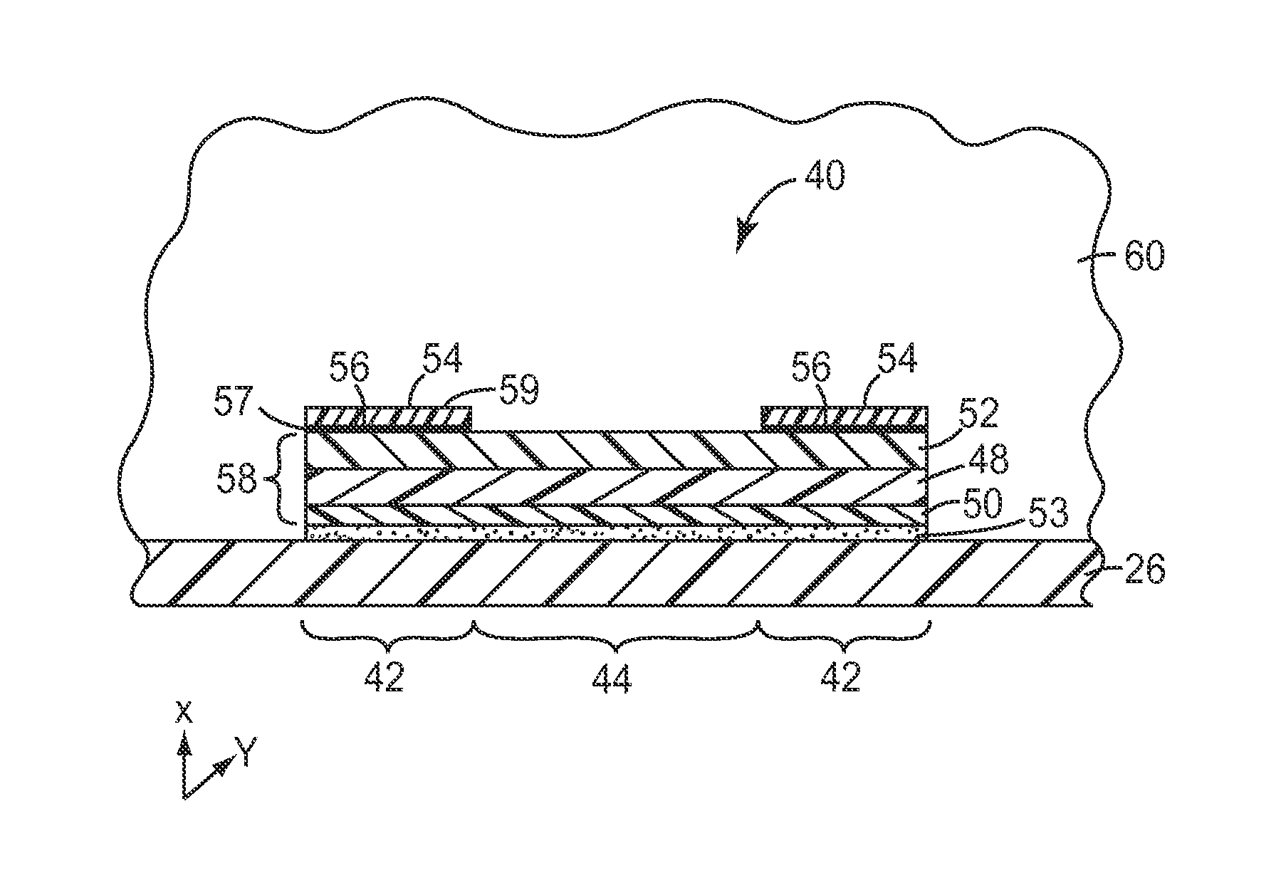
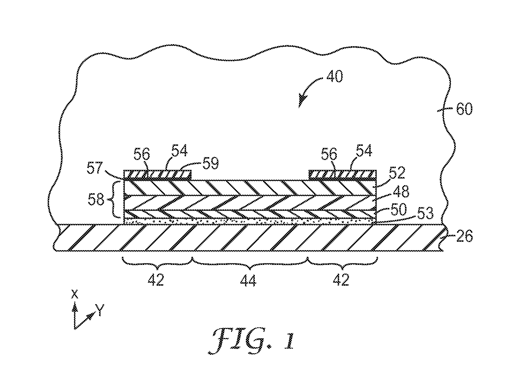
Image

Examples
example 1
[0107]An 8 ounce, narrow-mouthed amber bottle with Teflon®-wrapped threads was charged with 16.5 g of isobornyl acrylate (IBOA), 12.0 g of isooctyl acrylate (IOA), 1.5 g of acrylic acid (AA) and 70.0 g of ethyl acetate. Then 0.030 g of polymerization initiator (Vazo® 67) was added and the mixture was sparged with nitrogen for 15 minutes. The bottle was sealed with a Teflon®-lined metal cap, and further sealed with Teflon® tape and electrical tape. The bottle was placed in a water bath at 65° C. and gently tumbled. After 18 hours, the bottle was removed from the water bath and allowed to cool to room temperature. The resulting adhesive polymer composition had about 30 weight percent solids, and an IBOA / IOA / AA composition of about 55 / 40 / 5.
[0108]The glass transition temperature (Tg) of the polymer was calculated to be 13° C. The Tg was calculated using the Fox Equation: 1 / Tg=Σi(Wi / Tgi), wherein Tg is the glass transition temperature of the copolymer, W, is the weight fraction of monome...
examples 2-25
[0113]Adhesives were prepared and tested on ESLI sensor films according to the procedure described in Example 1 except as follows.
[0114]Adhesives for Examples 2-25 were prepared using the monomers shown in Table 1. Examples 2, 7, 9, 11, 13, and 15 included 1% by weight of the aziridine crosslinking agent prepared according to Preparative Example 1 of U.S. 2010 / 0227969.
[0115]Adhesives for Examples 16-25 were prepared with only IOA and IBOA.
[0116]Adhesives from Examples 1, 3, 4, and 5 were also tested after aging for 24 and 72 hours at 50° C. and at 80° C., respectively.
example c1-c3
[0117]C1 was a polyisobutylene adhesive prepared by dissolving about 10% by weight of a polyisobutylene (Oppanol® B150) in toluene and coating on a PET liner.
[0118]C2 was an acrylate adhesive prepared according the procedure of Example 1 with IOA, EA (ethyl acrylate) and AA and a ratio of 50:40:10, and coated on a PET liner.
[0119]C3 was an acrylate adhesive prepared according the procedure of Example 1 with BA (butyl acrylate), MA (methyl acrylate), and AA in a ratio of 58:40:2 and coated on a PET liner.
[0120]The adhesive-coated PET liners were taped to thin aluminum panels and dried in an oven set at 70° C. for 20 minutes followed by placing in an oven set at 120° C. for an additional 30 minutes. The adhesives were prepared with a dry thickness of about 2 mils (0.051 mm) and tested according the procedure of Example 1 on ESLI sensor films. Results are shown in Table 1.
TABLE 1Visual ChangeCompositionTg50° C.80° C.ExIOAIBOAAA° C.5 min10 min15 min30 min72 h24 h72 h14055513000000124055...
PUM
| Property | Measurement | Unit |
|---|---|---|
| Tg | aaaaa | aaaaa |
| Tg | aaaaa | aaaaa |
| Tg | aaaaa | aaaaa |
Abstract
Description
Claims
Application Information