Electrical system having a DC link

a technology of dc link and electric system, which is applied in the direction of battery/cell propulsion, emergency power supply arrangement, transportation and packaging, etc., can solve the problems of tripping the whole system, affecting the operation of the system, and the temporary power consumption of the loads connected to the dc link can be higher than the capacity of the main power source, so as to reduce the generated power, the effect of higher voltage value and higher voltage valu

Active Publication Date: 2014-01-09
ABB (SCHWEIZ) AG
View PDF2 Cites 14 Cited by
  • Summary
  • Abstract
  • Description
  • Claims
  • Application Information

AI Technical Summary

Benefits of technology

[0017]An advantage of the method and the system of the present disclosure is that the dynamic response to disturbances in the voltage is greatly improved. The dynamic control is no longer originated from a higher-level controller because each converter acts individually on the basis of the set voltage limits.
[0018]The method and the system improve the security of the operation by minimizing downtime. Even further, the energy capture in the system is better than in the known systems and improves the overall energy efficiency because the reaction times to changing conditions are faster.
[0019]The higher-level controller can still give instructions to separate converters. These instructions can be used to set reference values for converters and direct commands to converters in some special situations. However, the DC link voltage control is carried out by individual converters.

Problems solved by technology

Further, the power rating of the largest motors can be considerable compared with the capacity of the main power source, and the temporary power consumption of the loads connected to the DC link can be higher than the capacity of the main power source.
The problem relating to known system relates to voltage control of the DC link voltage.
As the higher-level controller is connected to the system by using communications interface, the control delays can lead to tripping of the whole system.
If, for example, the power of one load is suddenly changed, the power balance in the system is disturbed.
Due to communication delays in the power balance controller of the higher-level controller, the controller does not have enough time to react to the abruptly changed conditions and to adjust the reference values accordingly for the other converters of the system, and the whole electrical system can collapse.

Method used


Image

  • Electrical system having a DC link
  • Electrical system having a DC link
  • Electrical system having a DC link

Examples


Embodiment Construction

[0015]Exemplary embodiments of the present disclosure provide a method and a system for implementing the method which overcome the drawbacks associated with known techniques.

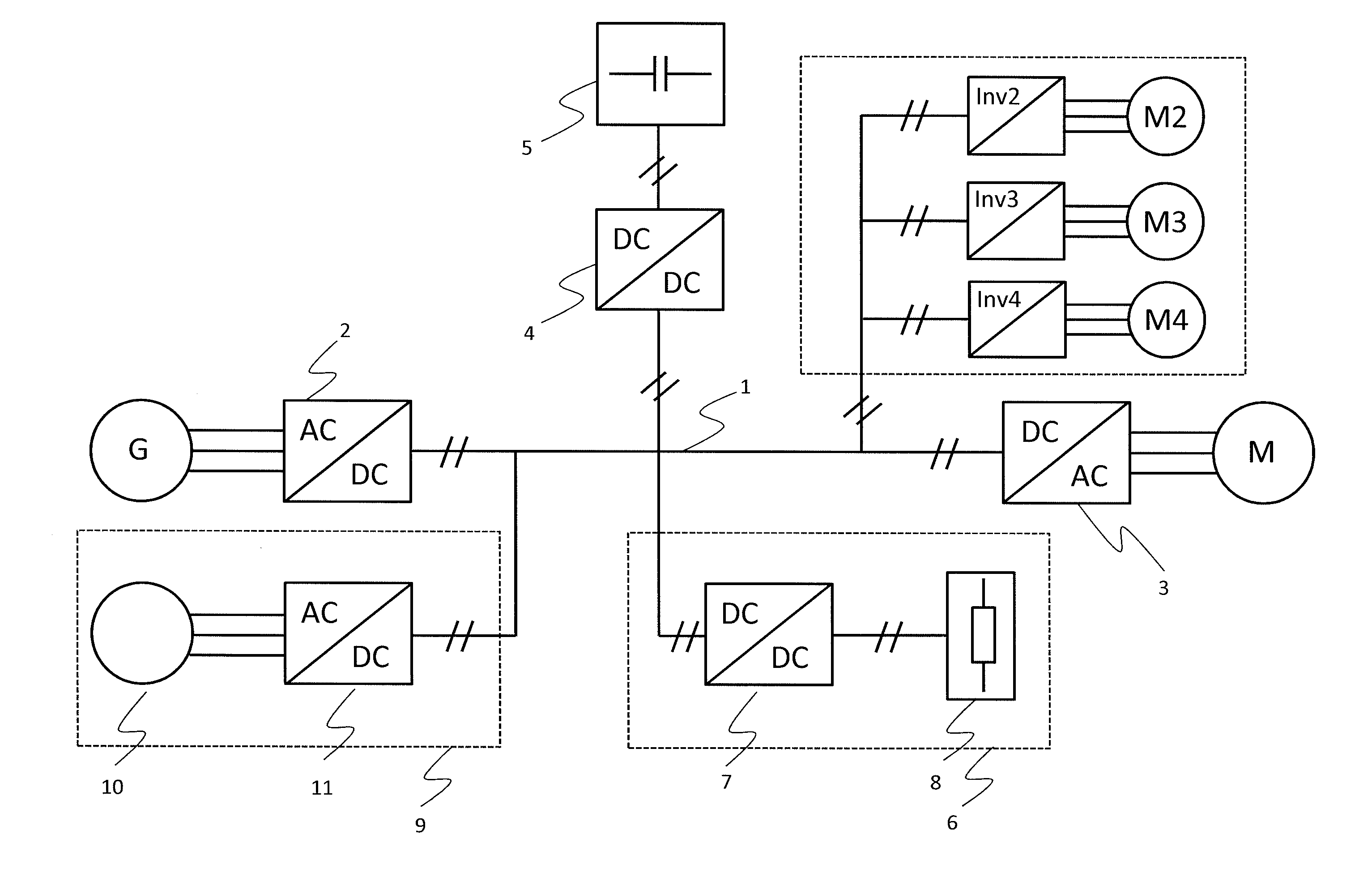
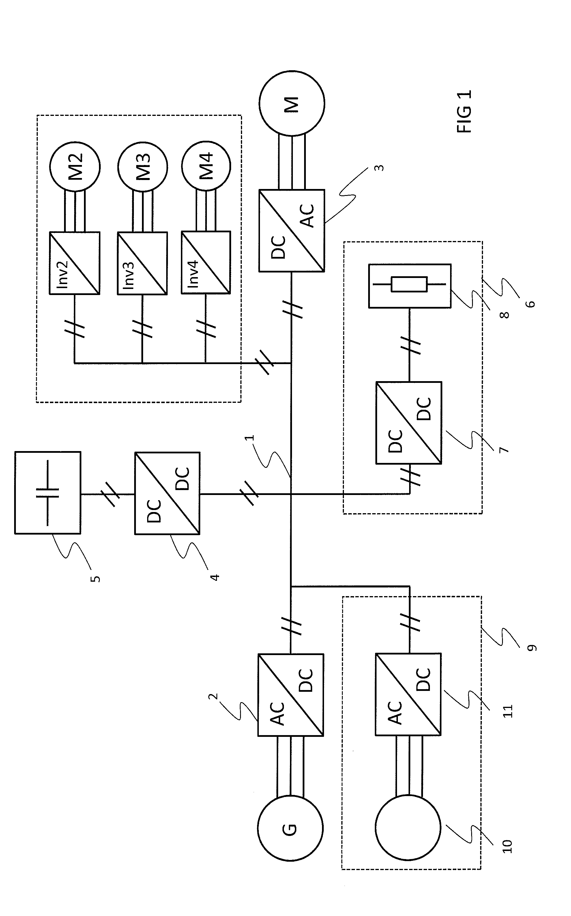
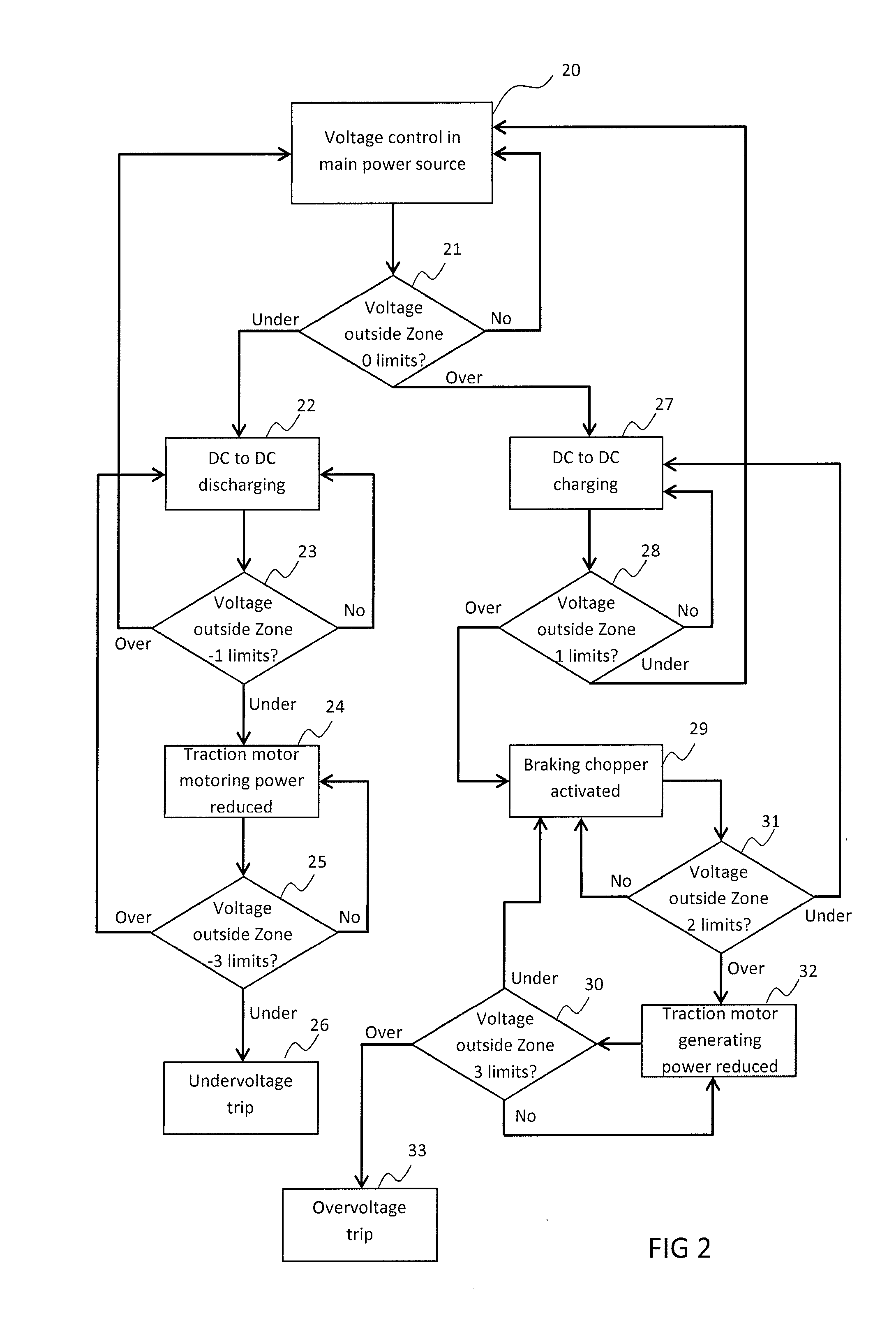
[0016]Exemplary embodiments of the present disclosure are based on the idea of using individual converters for controlling the DC voltage of the DC link. The responsibility for the voltage control is given to different converters, depending on the DC voltage. Each converter type has different voltage control areas. Each converter determines, on the basis of the DC voltage and set voltage areas, if they should control the DC voltage.

[0017]An advantage of the method and the system of the present disclosure is that the dynamic response to disturbances in the voltage is greatly improved. The dynamic control is no longer originated from a higher-level controller because each converter acts individually on the basis of the set voltage limits.

[0018]The method and the system improve the security of the operation by mini...


PUM


Abstract

An electrical system and method include a DC link, a controlled rectifier connected between the DC link and a power source, an energy storage, a DC to DC converter connected between the DC link and the energy storage, a motor, and a DC to AC converter connected between the DC link and the motor. The converters are configured to transfer power in both directions. The rectifier controls the DC voltage of the DC link when the DC link voltage is in a first voltage range. The DC to DC converter controls the DC voltage of the DC link by charging the energy storage when the DC link voltage is in a second voltage range, which has higher voltage values than the first voltage range, or by discharging the energy storage when the DC link voltage is in a third voltage range, which has lower voltages than the first voltage range.

Description

RELATED APPLICATION[0001]This application claims priority under 35 U.S.C. §119 to European Patent Application No. 12175493.1 filed in Europe on Jul. 9, 2012, the entire content of which is hereby incorporated by reference in its entirety.FIELD[0002]The present disclosure relates to electrical systems. More particularly, the present disclosure relates to electrical systems having a power source, one or more energy storages and one or more loads connected to a common DC link.BACKGROUND INFORMATION[0003]In an electrical system with a DC link, an electrical power source produces electrical power to a DC link to which one or more electrical motors are connected for driving a load. In such an electrical system, the electrical power source is, for example, a generator that is driven with a main power source, for example, a diesel engine. The diesel engine rotates the generator, and the generator output is rectified and fed to the DC link.[0004]The electrical motors connected to the DC link...

Claims


Application Information

Patent Timeline
Patent Type & Authority Applications(United States)
IPC IPC(8): H02J4/00B60L50/15
CPCH02J4/00B60L1/003B60L1/20B60L50/61Y02T10/62Y02T10/70Y02T10/7072
Inventor KOUKKARI, JUHALEPPINEN, TUOMORONKAINEN, TEEMU
Owner ABB (SCHWEIZ) AG
Why Eureka
Try Eureka