Acoustic transducer and interface circuit

a transducer and interface circuit technology, applied in the field of acoustic transducers, can solve the problems of deterioration of sound quality, difficulty for low-sensitivity microphones to detect small sound with high quality, mismatching of acoustic characteristics, etc., and achieve the effect of reducing the variation between chips

Active Publication Date: 2014-01-09
ORMON CORP +1
View PDF4 Cites 46 Cited by
  • Summary
  • Abstract
  • Description
  • Claims
  • Application Information

AI Technical Summary

Benefits of technology

[0021]The present embodiment describes an acoustic transducer which is capable of converting a sound wave into a plurality of electrical signals, and is capable of reducing the variations between the chips and the mismatching in the chip with regard to the acoustic characteristics. The present disclosure includes a digital electronic interface circuit for the acoustic transducer and a corresponding acoustic transducer system.
[0023]In accordance with the above configuration, at least one of the vibrating electrode and the fixed electrode is divided into divided electrodes, whereby a plurality of variable capacitors are formed between the vibrating electrode and the fixed electrode. This makes it possible to provide an acoustic transducer in which the plurality of divided electrodes respectively output the plurality of electrical signals, so that the sound wave is converted into the plurality of electrical signals.
[0024]Moreover, the plurality of variable capacitors are formed between the same vibrating membrane and the same fixed membrane. Hence, according to the present disclosure, the chips have similar variations between the detection sensitivities of the respective variable capacitors, in comparison with the conventional technique by which the plurality of vibrating membranes and the plurality of fixed membranes are provided independently. This makes it possible to reduce the variation between the chips with regard to the difference between the detection sensitivities of the variable capacitors. Moreover, the variable capacitors share the vibrating membrane and the fixed membrane. This makes it possible to reduce, in the chip, mismatching in the acoustic characteristics such as the frequency characteristics and the phases.
[0025]As described above, according to the acoustic transducer of the present disclosure, at least one of the vibrating electrode and the fixed electrode is divided into a plurality of divided electrodes, whereby the plurality of variable capacitors are formed between the vibrating electrode and the fixed electrode. This makes it possible to provide the acoustic transducer in which the plurality of divided electrodes respectively output a plurality of electrical signals, so that the sound wave is converted into the plurality of electrical signals. Moreover, the plurality of variable capacitors are formed between the same vibrating membrane and the same fixed membrane. This makes it possible to reduce the variation between the chips with regard to the difference between the detection sensitivities of the variable capacitors, and to reduce, in the chip, the mismatching in the acoustic characteristics such as the frequency characteristics and the phases.

Problems solved by technology

This is because attempting to detect a large sound by the microphone results in generation of a harmonic distortion in an output signal, thereby leading to deterioration of sound quality.
This is because the high-sensitivity microphone tends to output a large signal and therefore is likely to cause the THD.
However, it is difficult for the low-sensitivity microphone to detect a small sound with high quality.
However, according to the above configuration described in each of Japanese Unexamined Patent Publication No. 2008-245267 and U.S. Patent Application Publication No. 2007 / 0047746, the acoustic sensors are formed independently of one another, and therefore variation and mismatching in their acoustic characteristics occurs.
Since acoustic characteristics such as frequency characteristics and phases are affected by the back chamber and the vent hole, mismatching in the acoustic characteristics occurs in the chip.
This solution is not free from problems, due mainly to the complexity of the processing chain, to a relevant sensitivity to noise and oscillations of the input signal, and to a reduced configurability.

Method used


Image

  • Acoustic transducer and interface circuit
  • Acoustic transducer and interface circuit
  • Acoustic transducer and interface circuit

Examples


Embodiment Construction

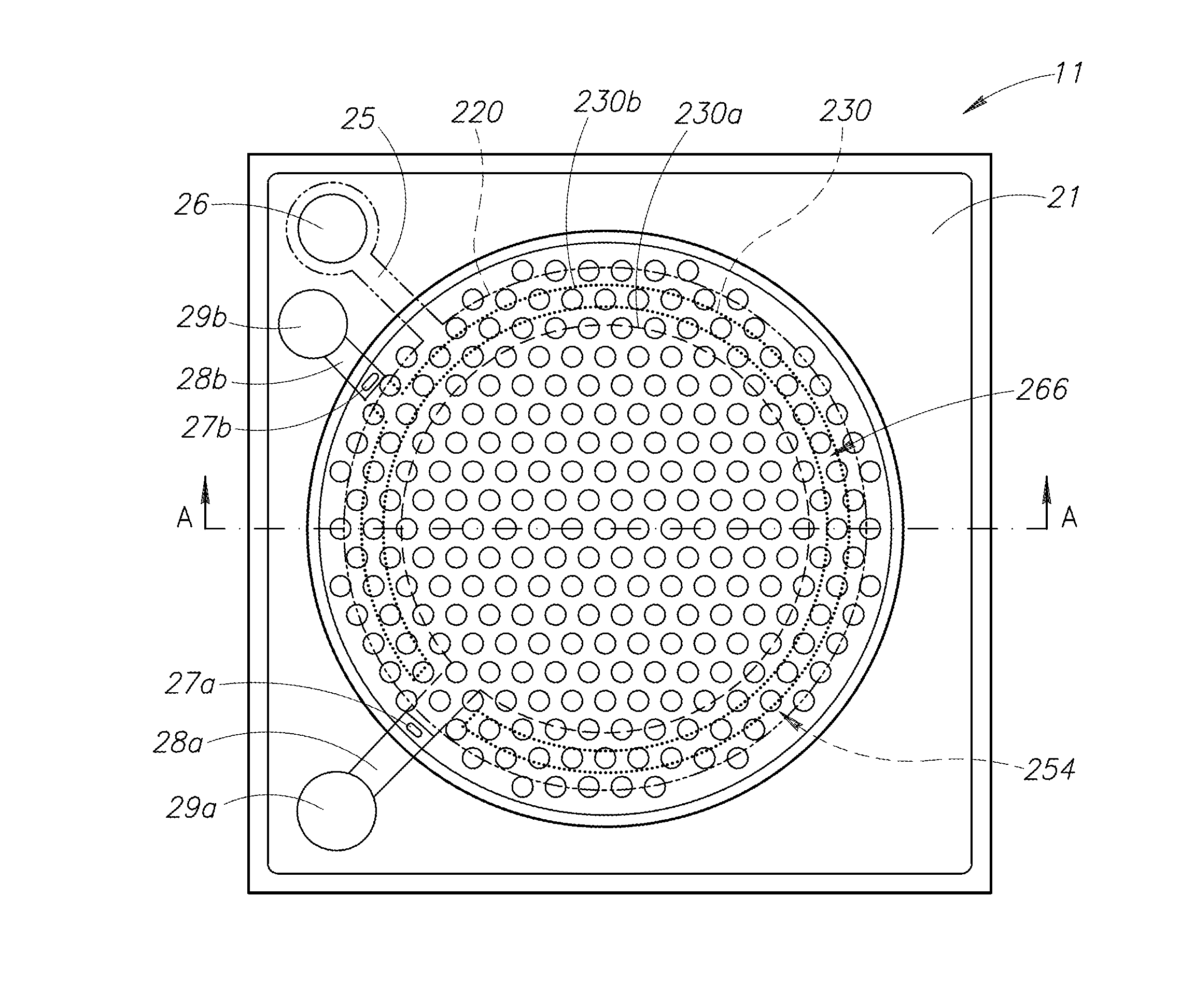
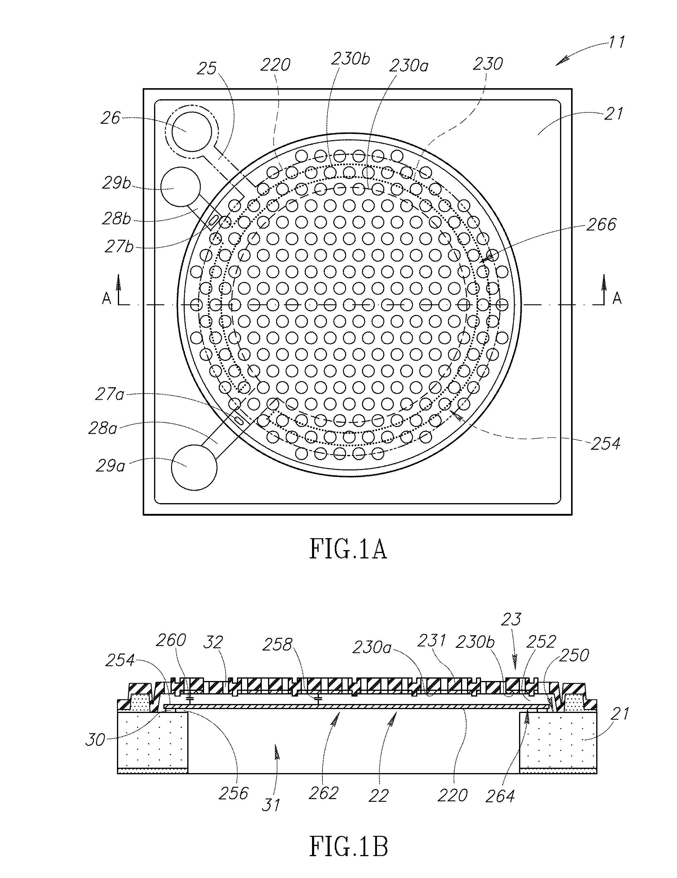
[0053]The following describes an embodiment of the present disclosure with reference to FIGS. 1A to 3. FIGS. 1A and 1B are top down and cross-sectional views of the acoustic sensor 11 in this embodiment. FIG. 1A is a top plan view of the acoustic sensor 11, and FIG. 1B is an enlarged cross-sectional view of the acoustic sensor 11, taken along line A-A shown in FIG. 1A and viewed in an arrow direction shown in FIG. 1A.

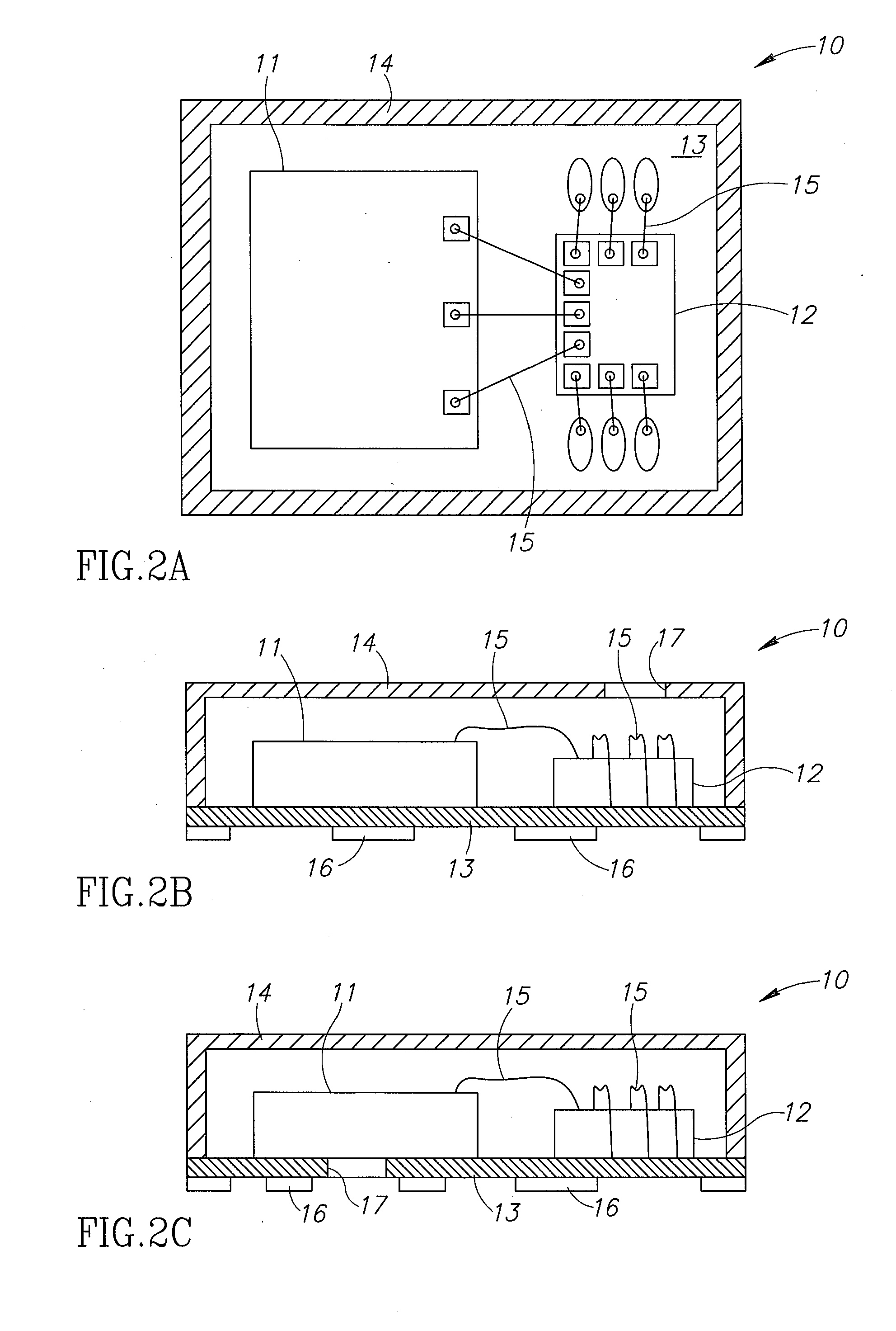
[0054]FIGS. 2A to 2C show a schematic configuration of a MEMS microphone package of this embodiment. FIG. 2A is a plan view showing a portion of the MEMS microphone package with an upper portion of the package cut away. FIGS. 2B and 2C are front views showing the MEMS microphone packages with a front portion cut away. Note that FIG. 2C is a modification of the configuration shown in FIG. 2B.

[0055]As shown in FIG. 2A, the MEMS microphone package 10 includes an acoustic sensor (acoustic transducer) 11, an ASIC 12, a wiring board or printed circuit board 13, and a cover 14...


PUM


Abstract

The present disclosure is directed to an acoustic transducer configured to detect a sound wave according to changes in capacitances between a vibrating electrode and a fixed electrode. At least one of the vibrating electrode and the fixed electrode being divided into a plurality of divided electrodes, and the plurality of divided electrodes outputting electrical signals. The disclosure includes a digital interface circuit coupled to the divided electrodes. The circuit includes a recombination stage, which supplies a mixed signal by combining the first digital processed signal and the second digital processed signal with a respective weight that is a function of a first level value of the first processed signal. An output stage is included, which supplies, selectively and alternatively, a first processed signal, a second processed signal, or a mixed signal.

Description

BACKGROUND[0001]1. Technical Field[0002]The present disclosure relates to an acoustic transducer having a split membrane that converts a sound wave into electrical signals, and to a digital electronic interface circuit for an acoustic transducer.[0003]2. Description of the Related Art[0004]Conventionally, Electret Condenser Microphones have been used as a miniature microphone mounted on a cellular (mobile) phone. The ECM is weak against heat. On the other hand, a MEMS microphone is superior to the ECM in terms of digitalization, miniaturization, enhancement of functionality / multi-functionality, and power savings. Accordingly, at present, the MEMS microphone is becoming widespread.[0005]The MEMS (microelectromechanical system) microphone includes a capacitor-type acoustic sensor (acoustic transducer) that detects a sound wave and converts the detected sound wave into an electrical signal (detection signal), a drive circuit that applies a voltage to the acoustic sensor, and a signal p...

Claims


Application Information

Patent Timeline
Patent Type & Authority Applications(United States)
IPC IPC(8): H04R3/00
CPCH04R3/00H04R1/086H04R19/005H04R19/016H04R31/00H01L2924/16152H01L2224/48137
Inventor KASAI, TAKASHISATO, SHOBUUCHIDA, YUKIPADOVANI, IGINODAVID, FILIPPOCONTI, SEBASTIANOZERBINI, MARTINOMOLINARI, LUCA
Owner ORMON CORP
Why Eureka
Try Eureka