
Chromatographic interface

Active Publication Date: 2014-01-16
WATERS TECH CORP
View PDF3 Cites 19 Cited by
  • Summary
  • Abstract
  • Description
  • Claims
  • Application Information

AI Technical Summary

Benefits of technology

The patent describes a system that uses an NMR assembly to analyze samples. The system includes a trap that can hold a sample and concentrate it. This helps to reduce interference from solvents and allows for automation of the analysis process. The system also uses a deuterated solvent to elute the sample from the trap, which helps to improve the accuracy of the analysis. Overall, the system makes the analysis process faster and more reliable.

Problems solved by technology

Such detectors were also susceptible to significant quantitation errors in the presence of overlapping chromatographic bands or zones, limiting their utility in the analysis of highly complex mixtures as are commonly encountered in biological and environmental applications.
There exist, however, important classes of compounds for which mass spectrometry alone is not capable of rendering a full and complete identification.
Knowledge of the chemical formula, while useful, is incomplete if the configuration or arrangement of the molecule is questionable or fully unknown.

Method used


Image

  • Chromatographic interface
  • Chromatographic interface
  • Chromatographic interface

Examples


Embodiment Construction

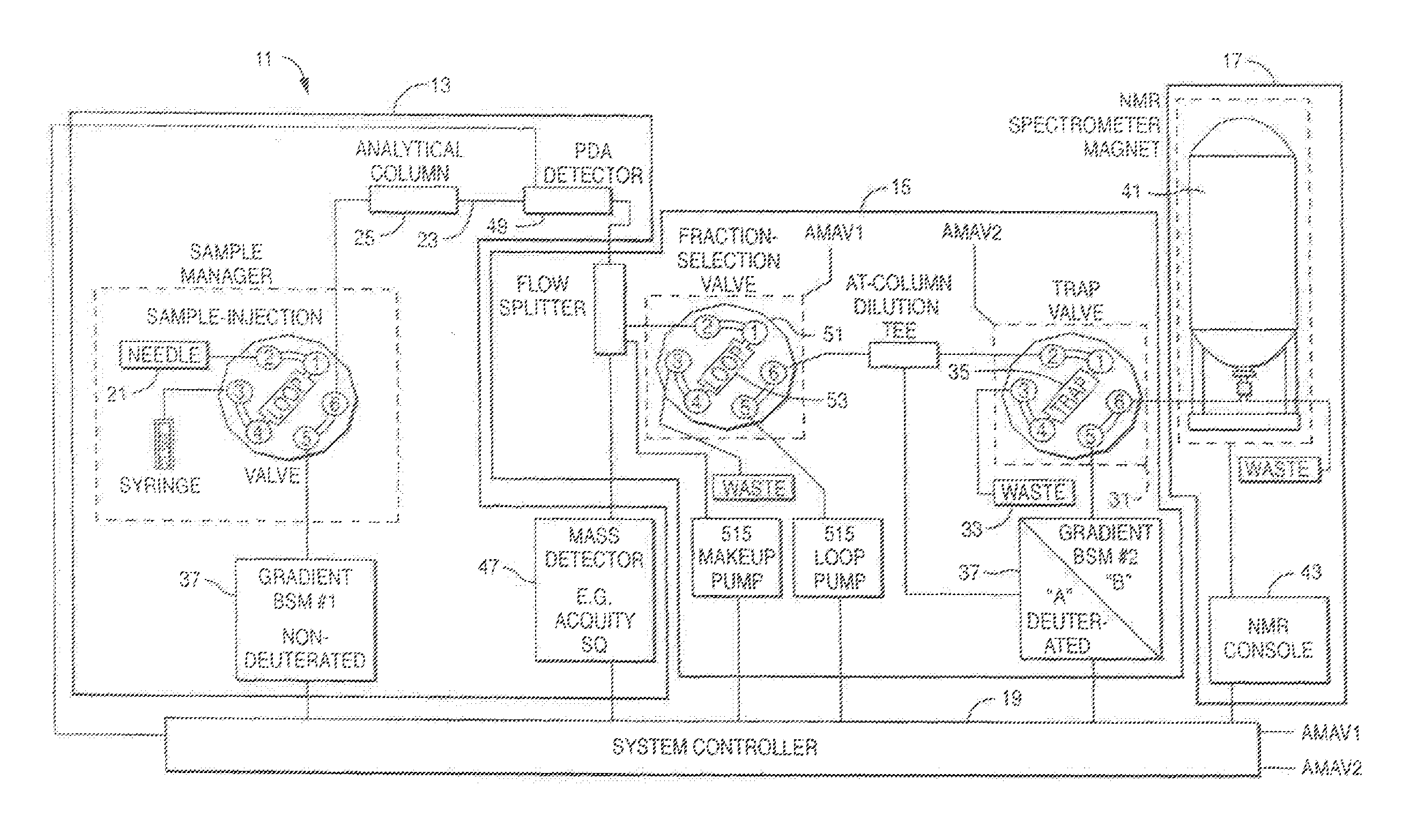
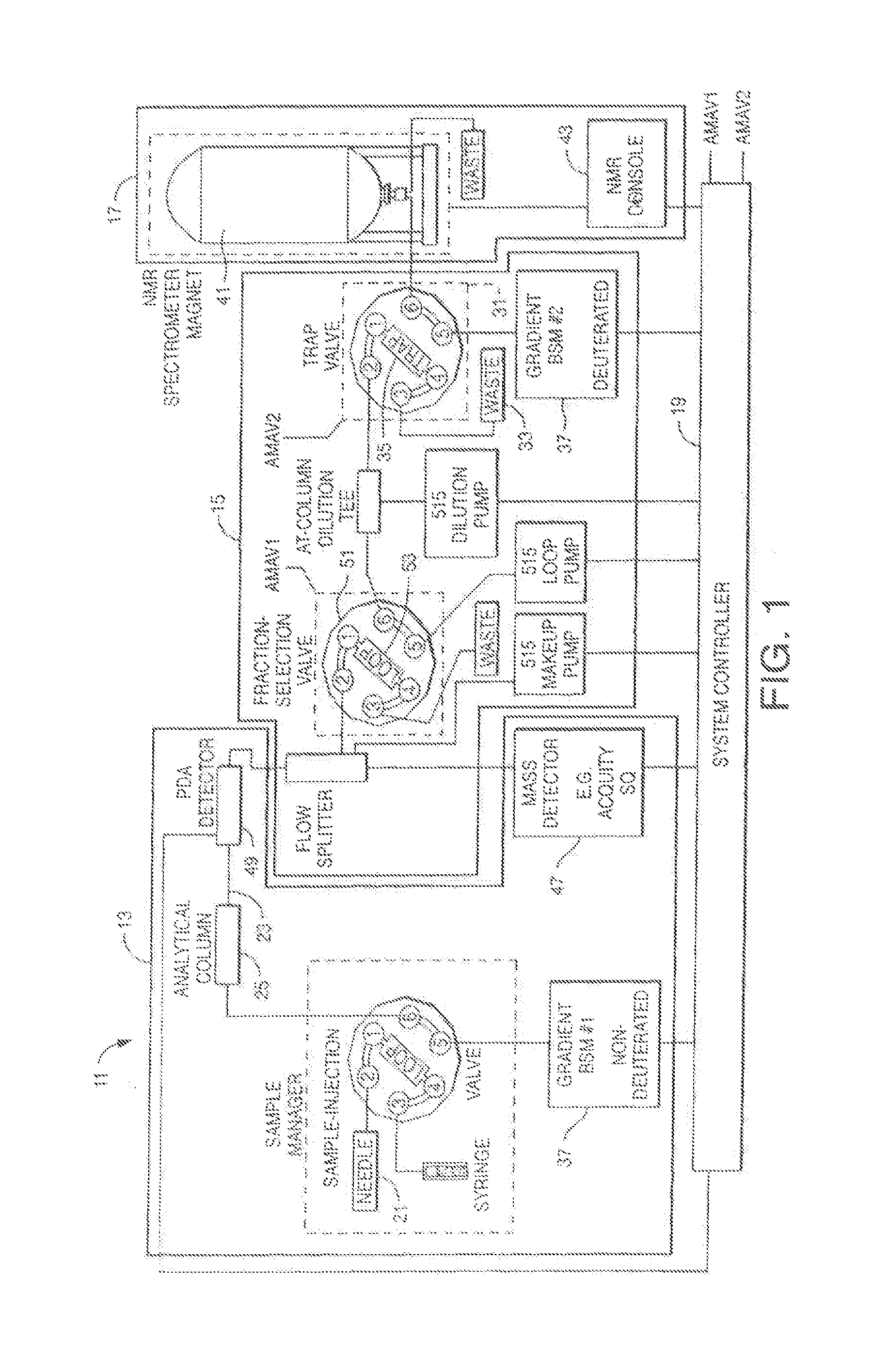
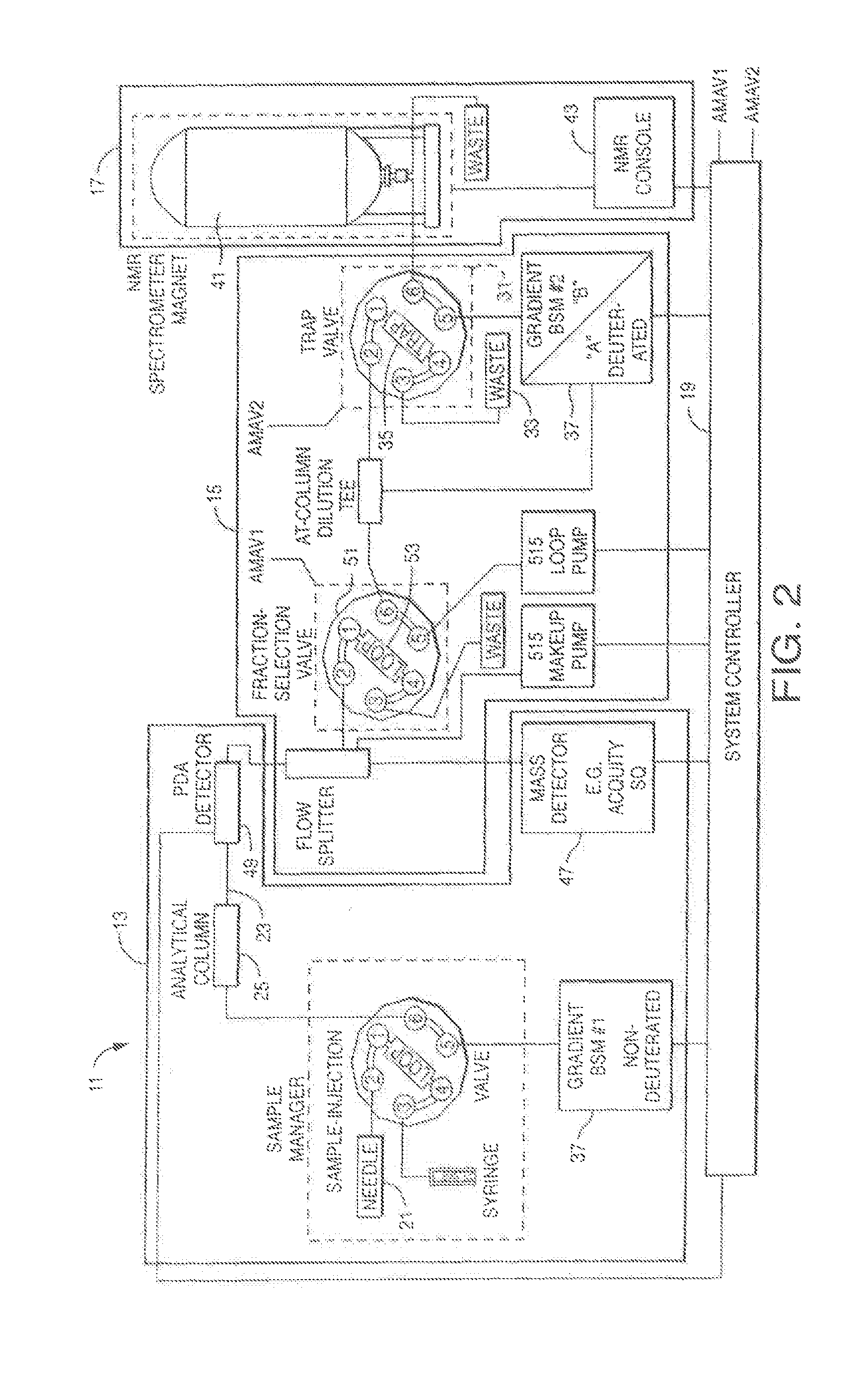
[0063]The present invention provides for interfacing between the separation (e.g., liquid chromatography “LC” supercritical fluid chromatography “SFC,” or any other fluid chromatography) of a sample and the analysis or study of the sample (e.g., by NMR, MS, SCD, or other assay such as a chemical assay or bioassay). In various aspects and embodiments, the present invention advantageously provides for the separation, handling, and focusing one or more analytes while interfacing between the chromatographic separation arid analysis of a sample. In NMR based application, the present invention further provides for the advantageous elimination of interference from protonated solvent(s).

[0064]With respect to apparatuses, the present invention provides for specialized chromatographic interfacing equipment. Apparatuses can include a sample acquisition unit (e.g., having an inflow selector, and outflow selector, one or more collection loops) and a specialized trapping unit (e.g., having a trap...


PUM


Abstract

An apparatus for chromatographic interfacing includes an interfacing unit, a sample acquisition unit, and a sample trapping unit. The interfacing unit includes (i) a chromatographic inflow valve adapted to receive a chromatographic sample separation flow, (ii) a chromatographic outflow valve adapted to allow discharge of the sample separation flow, (iii) a loop expulsion inflow valve adapted to receive an expulsion fluid flow, and (iv) a loop expulsion outflow valve in fluid communication with the loop expulsion inflow valve and adapted to allow discharge of a fluid. The sample acquisition unit includes (i) an inflow selector in selectable fluid communication with the chromatographic inflow valve or the loop expulsion inlet valve, (ii) an outflow selector in fluid communication with the loop expulsion outflow valve, and (iii) one or more collection loops, each loop being independently selectable to establish fluid communication between the inflow selector valve and the outflow selector valve. The sample trapping unit includes (i) a trap in selectable fluid communication with the loop expulsion outflow valve and defining a flow path from a first port to a second port and through a stationary phase disposed therebetween, the stationary phase adapted to trap an analyte of interest from a fraction of the chromatographic sample separation flow, and (ii) a scavenging gas source in selectable fluid communication with the flow path and a vacuum source in selectable fluid communication with the flow path, the scavenging gas source and vacuum source adapted to substantially dry the stationary phase.

Description

RELATED APPLICATIONS [0001]This application is a continuation in part of U.S. application Ser. No. 13 / 252,684 filed on Oct. 4, 2011, which is a continuation of International Application No. PCT / US2010 / 031194 filed on Ap. 15, 2010 and a continuation in pan of International Application No. PCT / US2010 / 030698 filed on Apr. 12, 2010, winch claims benefit of a priority to U.S. Provisional Application No. 61 / 168,306 filed on Apr. 10, 2009. The contents of all these applications are incorporated herein by reference in their entirety.FIELD OF THE INVENTION[0002]The invention, in various aspects and embodiments, relates generally to apparatuses and methods for chromatographic interfacing (e.g., sample handling and manipulation between separations or analyses). More particularly, the invention relates to apparatuses and methods for selectively collecting and / or preparing one or more analytes in a sample, and interfacing between essentially any type of liquid / fluid / condensed phase chromatograph...

Claims


Application Information

Patent Timeline
IPC IPC(8): G01N30/04
CPCG01N30/04G01N24/08G01N24/084G01N24/085G01R33/307G01R33/44G01N30/78G01N30/82G01N2030/8411G01R33/302G01R33/46
Inventor DOURDEVILLE, THEODORE A.PHOEBE, CHARLESGRIGAT, ROLF
Owner WATERS TECH CORP
Learn More