
Bioreactor for cell culture on a three-dimensional substrate

a three-dimensional substrate and cell culture technology, applied in bioreactors/fermenters, biomass after-treatment, biochemical apparatus and processes, etc., can solve the problems of generating turbulent flows in the flasks, significant shear levels on the surface of the substrate, and substrates that do not have sufficient mechanical performance characteristics to withstand significant transmural pressure, etc., to achieve the effect of reducing defiencies

Inactive Publication Date: 2014-01-30
UNIV DE PROVENCE D AIX MARSEILLE I +2
View PDF1 Cites 22 Cited by
  • Summary
  • Abstract
  • Description
  • Claims
  • Application Information

AI Technical Summary

Benefits of technology

The invention provides a new kind of bioreactor that can keep cells in suspension on a 3D substrate through a balance of different hydrodynamic forces. The device also prevents interactions between the substrates and walls, which can potentially degrade cell culture. The form of the culture chamber prevents impacts from materials in suspension. These improvements help to better control and maintain cell cultures.

Problems solved by technology

The main drawback with this technology lies in the fact that the diffusive exchanges, only present here, are generally insufficient to ensure the nutrition of the cells and in particular at the heart of the substrate.
The main drawback with this technology lies in the fact that the substrates have to be held on a specific support that will have to be removed before implantation.
Furthermore, this culture method often results in the generation of turbulent flows in the flasks and of significant shear levels on the surface of the substrates, both of which are prejudicial to the good development of the grafts.rotating wall bioreactors (Rotating Wall Vessels).
The main drawbacks with this technology lie in the fact that:a) premature cell death is observed because of the impacts between the substrates and between the substrates and the wall (centrifugation),b) there are engineering constraints (accurate control of the rotational movements requiring servo control, seals, etc.) and ergonomic constraints (assembly, dismantling, sampling, sterilization), often prohibitive for routine use because of the consequential excessive number of setting and operation parameters,Perfusion bioreactors.
The main drawback with this technology lies in the fact that some substrates do not necessarily have sufficient mechanical performance characteristics to withstand significant transmural pressures (given the size of the substrates provided).
However, these materials have mechanical characteristics that are inadequate for placement in the known bioreactors of the state of the art, and in particular the perfusion bioreactors described in the literature (held between “clamps”+application of a transmural pressure).
Such dimensions are not then realistic in the case of cell culture devices because of the high cost of the nutrient fluids.
Moreover, tests, transcribed in the literature on other bioreactors using sustentation of the substrates (rotating wall vessel bioreactors), have shown that the cell culture was potentially degraded by the interactions (impacts) between the substrates and the walls of the bioreactor.

Method used


Image

  • Bioreactor for cell culture on a three-dimensional substrate
  • Bioreactor for cell culture on a three-dimensional substrate
  • Bioreactor for cell culture on a three-dimensional substrate

Examples


examples

[0142]A—Prototype of a Bioreactor According to the Invention

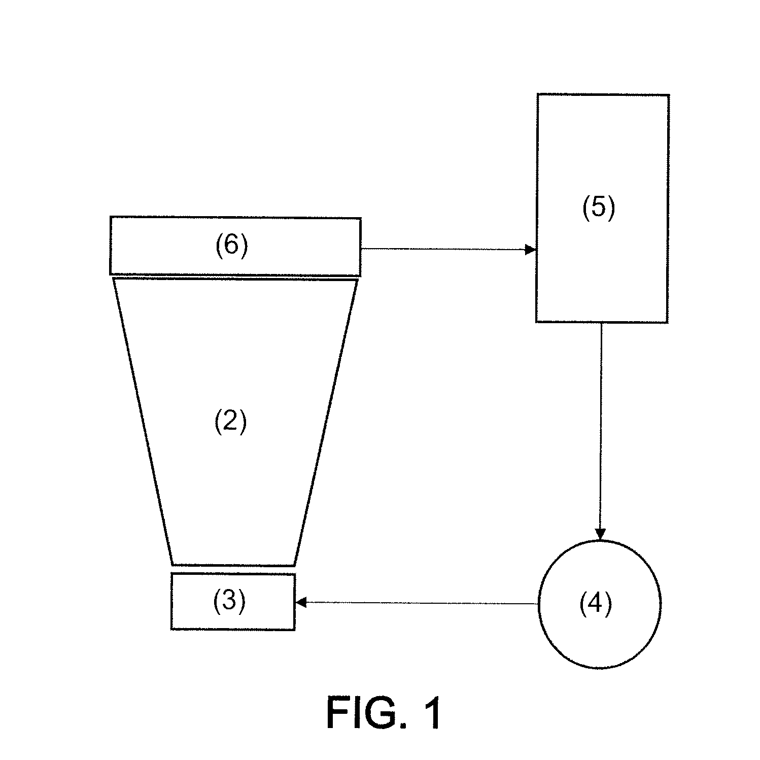
[0143]The inventors have produced the following prototype, as represented in FIGS. 2 to 6. The bioreactor comprises[0144]a culture chamber (represented in FIG. 2),[0145]an upstream flow-creating device,[0146]a downstream flow-creating device,[0147]pumping means and a tank.

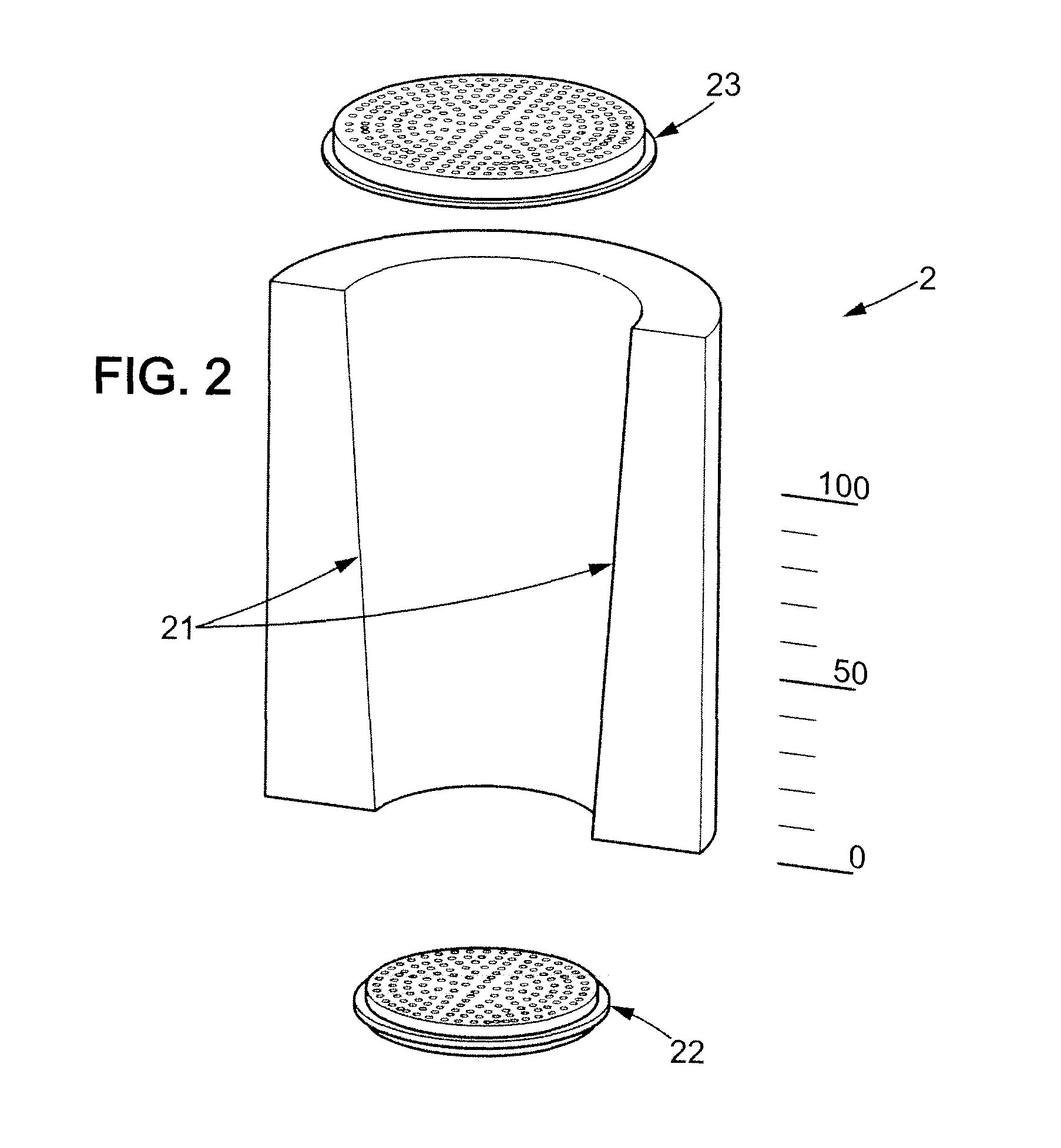
[0148]FIG. 2 represents a detailed view of the culture chamber comprising the culture chamber of cylindrical type (2), the inner walls (21) of which form an inverted cone. At the inlet of the culture chamber, there is a perforated grating (22) promoting the annular flow of the culture medium in the culture chamber. There is also a perforated grating (23) placed at the outlet, preventing the grafts from circulating in the rest of the device.

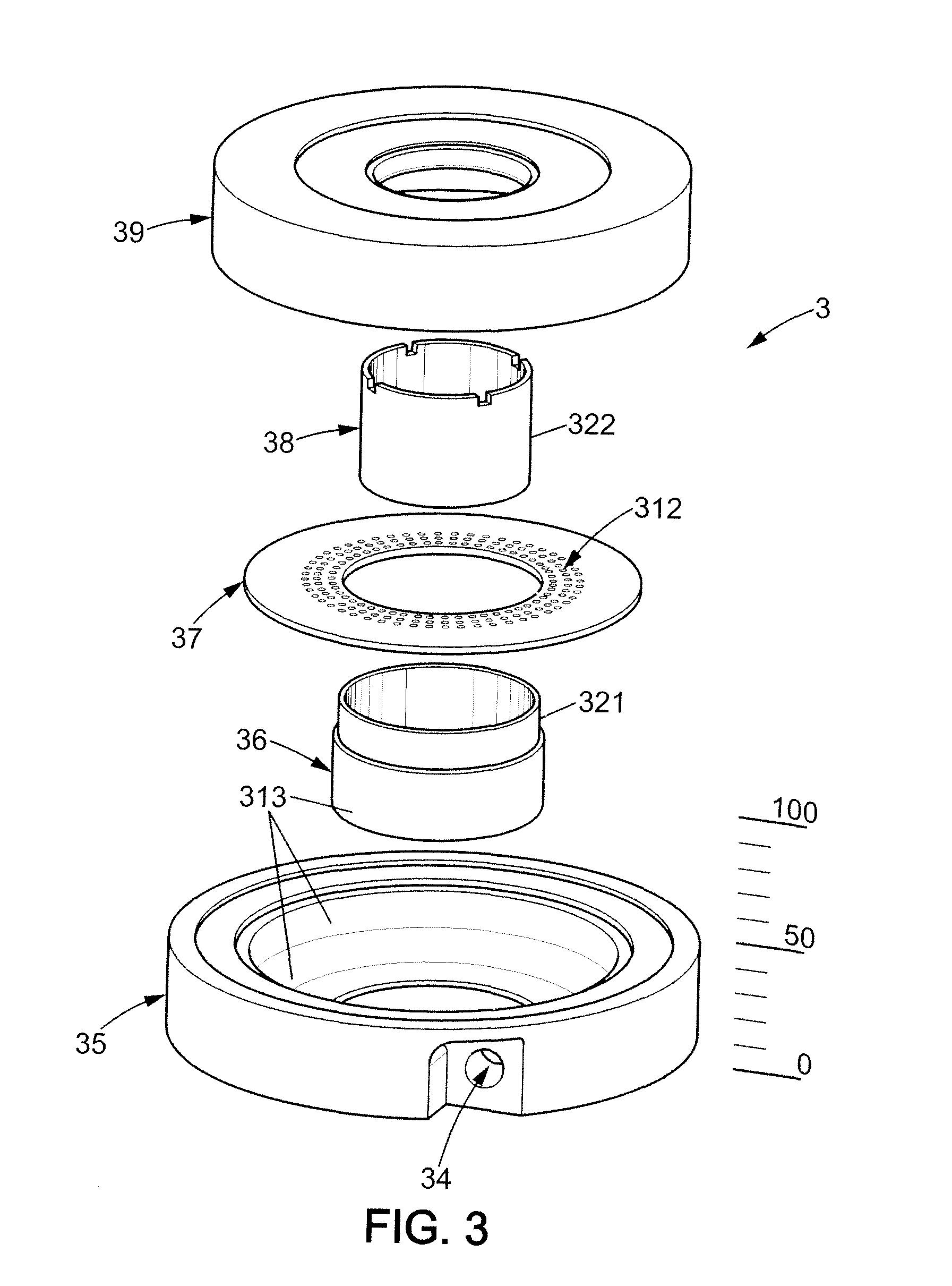
[0149]FIG. 3 represents a detailed view of the upstream flow-creating device and comprises, in particular, a perforated ring (35) allowing the culture medium to flow in an inner radius (31), two concentric cylinders (36)...


PUM


Abstract

The invention relates to a bioreactor (1) for cell culture on a three-dimensional substrate, comprisinga culture chamber (2), the inner walls of which form a vertical duct, preferably, tapered, with a diameter that widens regularly form the duct inlet to the duct outlet, means (3, 4) enabling the culture medium to flow in said vertical duct.The invention also relates to the advantageous use of these bioreactors in tissue engineering, for the production of tissue grafts, notably a bone or cartilage graft.

Description

FIELD OF THE INVENTION[0001]The invention relates to the field of bioreactors for cell culture. In particular, the invention relates to a bioreactor (1) for cell culture on a three-dimensional substrate, comprising: a culture chamber (2), the inner walls of which form a vertical duct, preferably tapered, with a diameter that widens regularly from the duct inlet to the duct outlet, means (3, 4) enabling the culture medium to flow in said vertical duct.[0002]The invention also relates to the advantageous use of these bioreactors in tissue engineering, for the production of tissue grafts, notably hone or cartilage grafts.CONTEXT OF THE INVENTION[0003]The aim of tissue engineering is to apply the principles of biology and of engineering in order to develop functional substitutes for injured tissues. Technological developments in tissue engineering should make it possible to obtain, from patient cells, tissues cultivated in vitro that can be tolerated by the organism and replace the inju...

Claims


Application Information

Patent Timeline
IPC IPC(8): C12M1/34
CPCC12M41/44C12M21/08C12M23/02C12M29/10C12M29/12C12M35/08C12M41/00
Inventor DEPLANO, VALERIEKNAPP, YANNICKBERTRAND, ERIC
Owner UNIV DE PROVENCE D AIX MARSEILLE I
Learn More