System, device and method for ablation of a vessel's wall from the inside

a technology of ablation and internal wall, which is applied in the field of bodily vessel treatment, can solve the problems of severe decrease in quality of life, death and hospitalization, and worsening of heart failure, and achieve the effect of increasing the temperature of the ablation region

Active Publication Date: 2014-01-30
MEDICAL DEV TECH
View PDF11 Cites 39 Cited by
  • Summary
  • Abstract
  • Description
  • Claims
  • Application Information

AI Technical Summary

Benefits of technology

[0062]external energy-providing means, which are spatially separated from the implant device and able to provide energy t...

Problems solved by technology

Despite incessant therapeutic improvements, cardiac disease remains the most important cause of death and hospitalizations in the western society.
Patients experiencing AF suffer from palpitations, fatigue, severe decrease in quality of life, worsening of heart failure, cerebral stroke, increased mortality and many other symptoms.
Prevalence and incidence of AF is gradually increasing thus causing AF to reach epidemic proportions.
So far, anti-arrhythmic drug treatment for AF is characterized by two major findings: inefficacy and/or intolerable side effects.
These drugs have a rather low efficiency ranging between 20 to 40%.
Initiating and continuing these drugs requires close monitoring of the patient as these drugs in itself can easily induce life threatening arrhythmias.
However, the list of possible side effects is practically unlimited: severe thyroid problems, severe lung disease, irreversible tinting of the skin, visual defects, possible carcinogenic nature, etc.
Soon enough, it was discovered that even a small gap of for example 1 mm in the line encircling the PV's could lead to electrical reconnection of the PV's and hence failure of the procedure with reoccurrence of AF.
Nevertheless, curing a patient from AF in a safe and effective manner remains a big hurdle in electrophysiology.
However, with this first group of procedures, it is not always guaranteed that a continuous line is formed with any gaps.
In some cases, a gap of the order of 1 mm may already be too wide to ensure a successful outcome of the PVI procedure.
In these cases, a repetition of the whole procedure with the accompanying danger, discomfort, cost, etc. for the patient, is usually deemed necessary.
New imaging techniques shortened these laborious procedures to about four to six hours.
T...

Method used


Image

  • System, device and method for ablation of a vessel's wall from the inside
  • System, device and method for ablation of a vessel's wall from the inside
  • System, device and method for ablation of a vessel's wall from the inside

Examples


examples

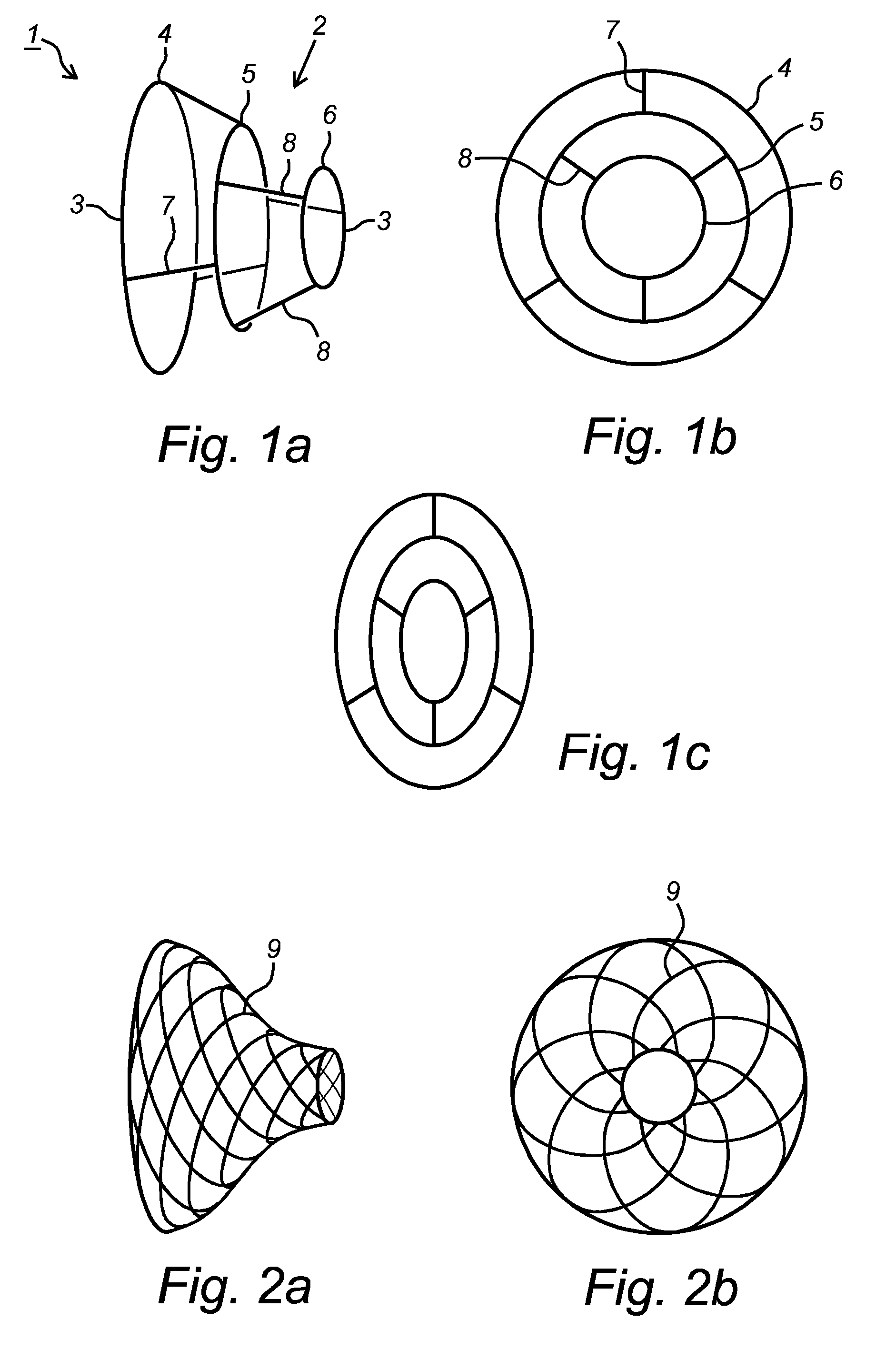
[0225]FIG. 1 represents a preferred embodiment of an implant 1 according to the present invention with circular cross-section (FIG. 1B) and elliptic cross-section (FIG. 1C). It should be clear that in the other figures showing embodiments of implants, the cross-sections can also be circular or elliptical, or basically any other shape which fits the vessel into which it is to be implanted best.

[0226]The represented implant 1 comprises a body 2, in this case shaped as narrowing tubular cage and made of metal wires 3 or the like, suitable to be placed inside the antrum of a pulmonary vein.

[0227]More in particular, the body 2 is provided of in this case three circular wires, a first bigger circular wire 4, an intermediate mid-sized second circular wire 5, and a third smaller circular wire 6.

[0228]The outlook of the body 2 may though be provided of more or less than three rings, for example two to five, more specifically three to four, or even more than five rings.

[0229]The first bigger ...


PUM

PropertyMeasurementUnit
Temperatureaaaaaaaaaa

Abstract

The current invention concerns systems, devices and methods for the ablation of a vessel's wall from the inside, more specifically to implant devices and to the ablation of the wall of one or more pulmonary veins (PV) from the inside, preferably transmural ablation and preferably at the level of the antrum. Hereby, one or more implant devices can be implanted in the vessels and can subsequently be heated by external energy-providing means.

Description

TECHNICAL FIELD[0001]The invention pertains to the technical field of the treatment of bodily vessels by means of ablation, more specifically to the treatment of cardiac conditions such as atrial fibrillation (AF). In particular, the present invention relates to systems, devices and methods for the ablation of a vessel's wall from the inside, more specifically to implant devices and to the ablation of the wall of one or more pulmonary veins (PV) from the inside, preferably transmural ablation and preferably at the level of the antrum.BACKGROUND[0002]The present invention concerns a system of one or more implant devices and excitation device, an implant device and a method using the system and one or more devices for the treatment of arterial and venous structures.[0003]The present invention also concerns implant devices, a system of implant devices and external excitation means, and a method for positioning one or more implant devices in a vessel, and subsequently heating these impl...

Claims


Application Information

Patent Timeline
IPC IPC(8): A61B18/04
CPCA61B18/04A61B18/082A61B18/10A61B18/18A61F2/90A61M25/09A61N1/406A61B2018/00154A61B2018/00095A61B2018/00577A61B2018/00511A61B2018/00434A61B2018/00375A61B2018/00404A61B2018/00345A61B2018/00214A61B2018/00708A61B2018/00714A61B2018/0072A61B2018/00678A61B2018/00791A61B2018/00982A61F2/06A61F2210/0057A61F2250/0001A61F2220/0008A61N2/02A61B2090/3966
Inventor SCHWAGTEN, BRUNOVAN LANGENHOVE, GLENN
Owner MEDICAL DEV TECH
Why Eureka
Try Eureka