Three-dimensional image display apparatus

a three-dimensional image and display apparatus technology, applied in the direction of liquid crystal compositions, chemistry apparatus and processes, instruments, etc., can solve the problems of insufficient adhesion the occasional damage of the patterned retarder, so as to improve the productivity of the three-dimensional image display apparatus using the patterned retarder

Inactive Publication Date: 2014-02-20
JNC CORP +1
View PDF4 Cites 11 Cited by
  • Summary
  • Abstract
  • Description
  • Claims
  • Application Information

AI Technical Summary

Benefits of technology

[0016]When a peeling preventive agent including a polymerizable compound having a polar group, and a polymer having a polar group is added to a polymerizable liquid crystal compound, a patterned retarder is obtained in which adhesion between polymerizable liquid crystal layer 303, and alignment film 302 subjected to patterned alignment treatment and formed on tra...

Problems solved by technology

However, a patterned retarder consisting of the polymerizable liquid crystal compound has a problem of insufficient adhesion with regard to an interface between the alignment layer and a polymerizable liquid crystal layer.
If the adhesion is insufficient, for example, when a protective film is stuc...

Method used


Image

  • Three-dimensional image display apparatus
  • Three-dimensional image display apparatus
  • Three-dimensional image display apparatus

Examples


example 1

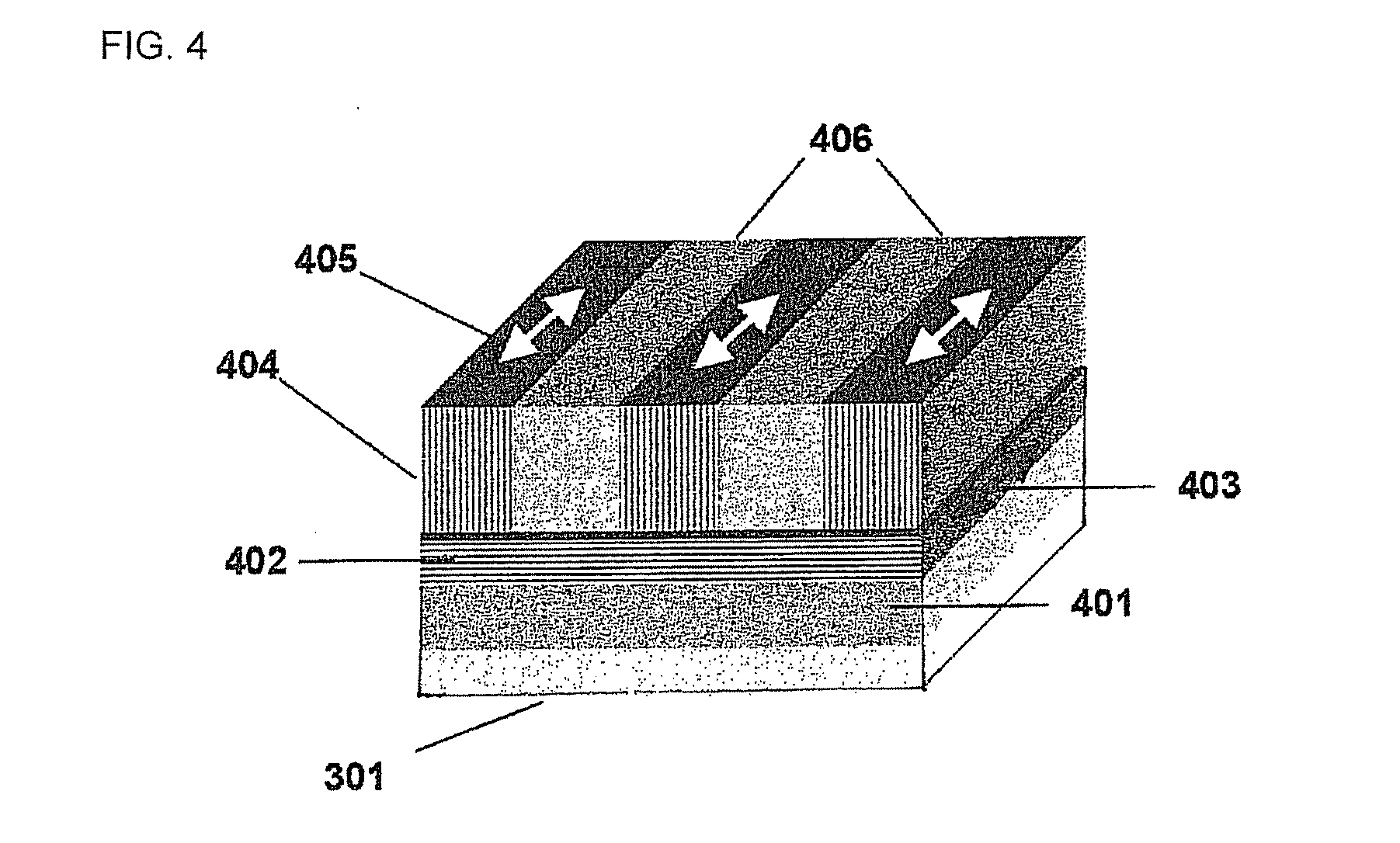
[0161]As transparent support substrate 301, a film having a thickness of 60 micrometers prepared using triacetyl cellulose was prepared. On the transparent support substrate 301, an aligning agent (a copolymer of 2-[4-[(E)-2-methoxycarbonylvinyl]phenoxy]ethyl-2-methylacrylate (A component) and 2-hydroxyethyl methacrylate (B component), a copolymerization ratio=A component / B component=7 / 3 (weight ratio), weight average molecular weight: approximately 70,000, solvent: toluene / 1-methoxy-2-propanol=1 / 1 (weight ratio), polymer concentration: 5 wt %) was applied by means of a spin coater, an applied surface was dried at 100° C. for 1 minute, and thus alignment film 302 having a thickness of 0.1 micrometer was formed. An applied surface of the alignment film was exposed, using a mask patterned in a stripe shape, with linearly polarized ultraviolet light having a wavelength near 313 nanometers from a direction of 90 degrees relative to the applied surface. In exposure, the applied surface w...

example 2

[0166]A patterned retarder was prepared in a manner similar to the operations in Example 1 except that, based on the total weight of the polymerizable liquid crystal compound, 1% by weight of 2-acryloyloxyethyl succinate (LIGHT ACRYLATE (registered trademark) HOA-MS (N), made by Kyoeisha Chemical Co., Ltd.) was added as a peeling preventive agent. When adhesion with regard to the patterned retarder obtained was evaluated in a manner similar to the operations in Example 1, a film remaining ratio in a polymerizable liquid crystal layer region in the patterned retarder was 100%.

example 3

[0167]A patterned retarder was prepared in a manner similar to the operations in Example 1 except that, based on the total weight of the polymerizable liquid crystal compound, 3% by weight of an aminated acrylic polymer (POLYMENT (registered trademark) NK-380, made by Nippon Shokubai Co., Ltd.) was added as a peeling preventive agent. When adhesion with regard to the patterned retarder obtained was evaluated in a manner similar to the operations in Example 1, a film remaining ratio in a polymerizable liquid crystal layer region in the patterned retarder was 100%.


PUM


Abstract

To provide a three-dimensional image display apparatus having patterned retarder 303 that is excellent in adhesion between transparent support substrate 301 and alignment film 302. A mixture containing a polymerizable liquid crystal compound and a peeling preventive agent is prepared. Here, the peeling preventive agent has as a polar group any one of a hydroxyl group, a carboxyl group, a phosphate group, a sulfonate group, an amino group, a mercapto group and an isocyanate group, and also has a polymerizable group. Then, an alignment layer is arranged on a transparent support substrate, and subjected to patterned treatment, and the mixture is coated, and a coated surface is dried and cured to form a patterned retarder, and thus a three-dimensional image display apparatus having excellent reliability, such as adhesion, is obtained.

Description

CROSS-REFERENCE TO RELATED APPLICATIONS[0001]This application claims the benefit of Japanese Patent Application No. 2012-181934, filed Aug. 20, 2012, in the Japanese Patent Office, all disclosures of the document(s) named above are incorporated herein by reference.BACKGROUND OF THE INVENTION[0002]1. Field of the Invention[0003]The present invention relates to a three-dimensional image display apparatus. In particular, the invention relates to a three-dimensional image display apparatus having an image-forming unit, and a polarization-axis control plate for outgoing, upon incoming of right-eye image light including a right-eye image and left-eye image light including a left-eye image as formed in the image-forming unit, the image light as linearly polarized light in which polarization axes are crossed at a right angle with each other, or circularly polarized light in which directions of rotation of the polarization axes are in a reverse direction with each other.[0004]2. Description ...

Claims


Application Information

Patent Timeline
IPC IPC(8): G02F1/1337G02B30/25
CPCG02F1/1337H04N13/337B32B2457/202G02B30/25C09K2323/03C09K2323/02G02F1/133631C09K2019/546C09K2019/528C09K19/542C09K2019/548
Inventor HIRAI, YOSHIHARU
Owner JNC CORP
Why Eureka
Try Eureka