Hydrocarbon and Divalent Cation Removal from Rich Mono ethylene Glycol (MEG) Feed Streams by Regenerable Filters

a monoethylene glycol and filter technology, applied in the direction of oxygen-containing compound preparation, multi-stage water/sewage treatment, separation process, etc., can solve the problem of increasing the abrasive nature of rich meg, reducing the settling of salt crystals, and excessive concentrations for optimal operation of the meg reclamation process. , to achieve the effect of reducing the volume, footprint and cost of processing equipment, facilitating the disposal of waste streams, and simplifying the hydrocarbon and divalen

Inactive Publication Date: 2014-02-27
CAMERSON INT CORP
View PDF4 Cites 6 Cited by
  • Summary
  • Abstract
  • Description
  • Claims
  • Application Information

AI Technical Summary

Benefits of technology

[0011]Objects of this invention are to (1) provide a more efficient process to remove hydrocarbons and divalent cations from a rich MEG feed stream before it enters the reclamation process; (2) simplify the hydrocarbon and divalent cation removal processes; (3) reduce the vo...

Problems solved by technology

When the oil properties are in the range of a light condensate, the hydrocarbon content may range from 100 ppm to 200 ppm, but even these concentrations may be excessive for optimal operation of the MEG reclamation process.
As more of this material forms, it increases the rich MEG' s tendency to form a stable foam, reduces the settling of salt crystals, increases the abrasive nature of the rich MEG so that pump seal failure and pipe erosion are more prevalent, and discolors the salt produced in the reclamation process making it unsuitable for marine discharge.
In offshore operations, excessive hydrocarbon levels in the rich MEG feed stream can also cause plugging of the downstream lean MEG injection nozzles if the hydrocarbons form a solid compound under line or injection conditions.
As a final example, hydrocarbons in the rich MEG feed stream may coat the ion exchange resin, reducing the efficiency of any process to remove divalent cations.
Hydrocarbon removal beyond the final production separator is currently limited.
However, because activated charcoal filters are not ...

Method used


Image

  • Hydrocarbon and Divalent Cation Removal from Rich Mono ethylene Glycol (MEG) Feed Streams by Regenerable Filters
  • Hydrocarbon and Divalent Cation Removal from Rich Mono ethylene Glycol (MEG) Feed Streams by Regenerable Filters

Examples


Embodiment Construction

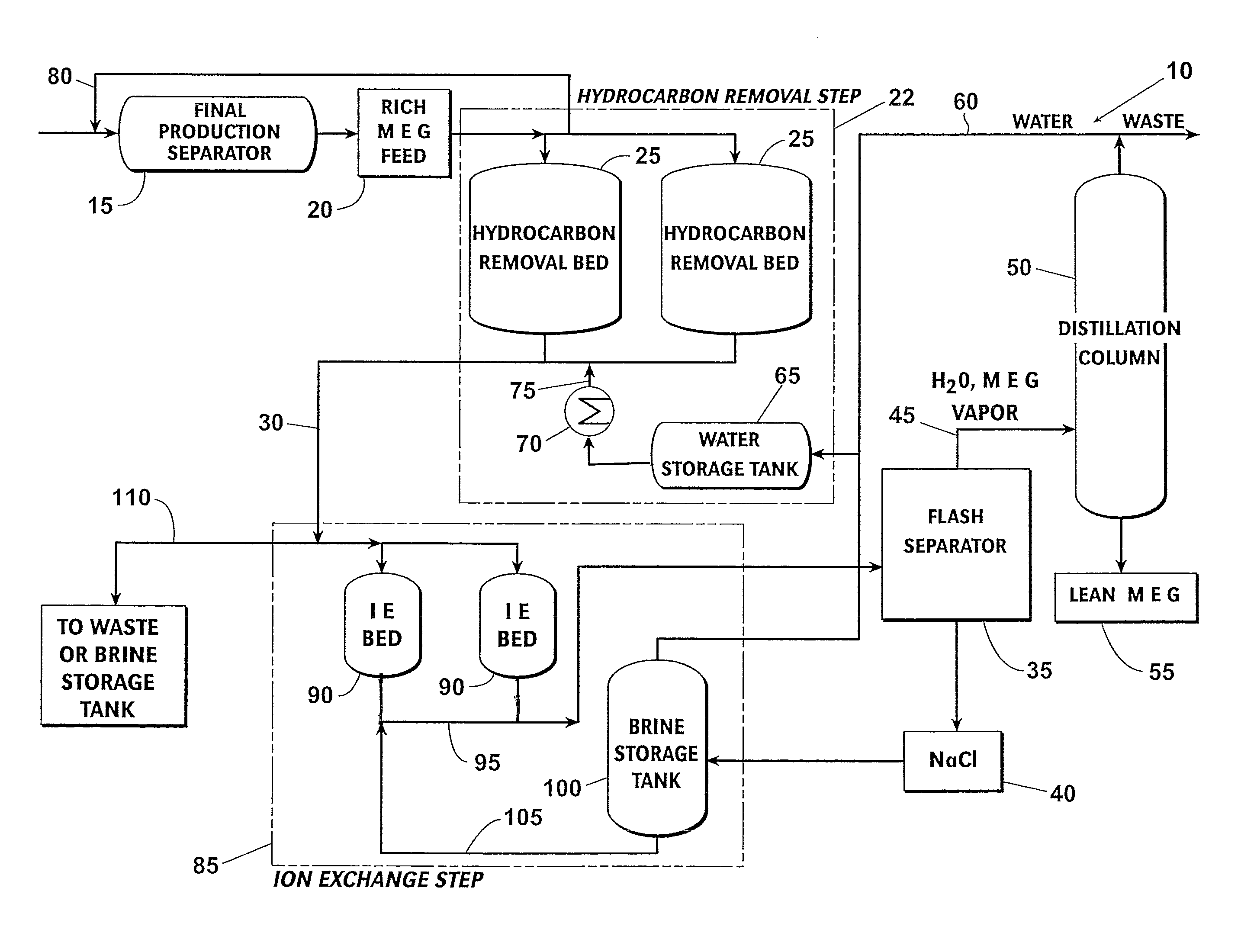
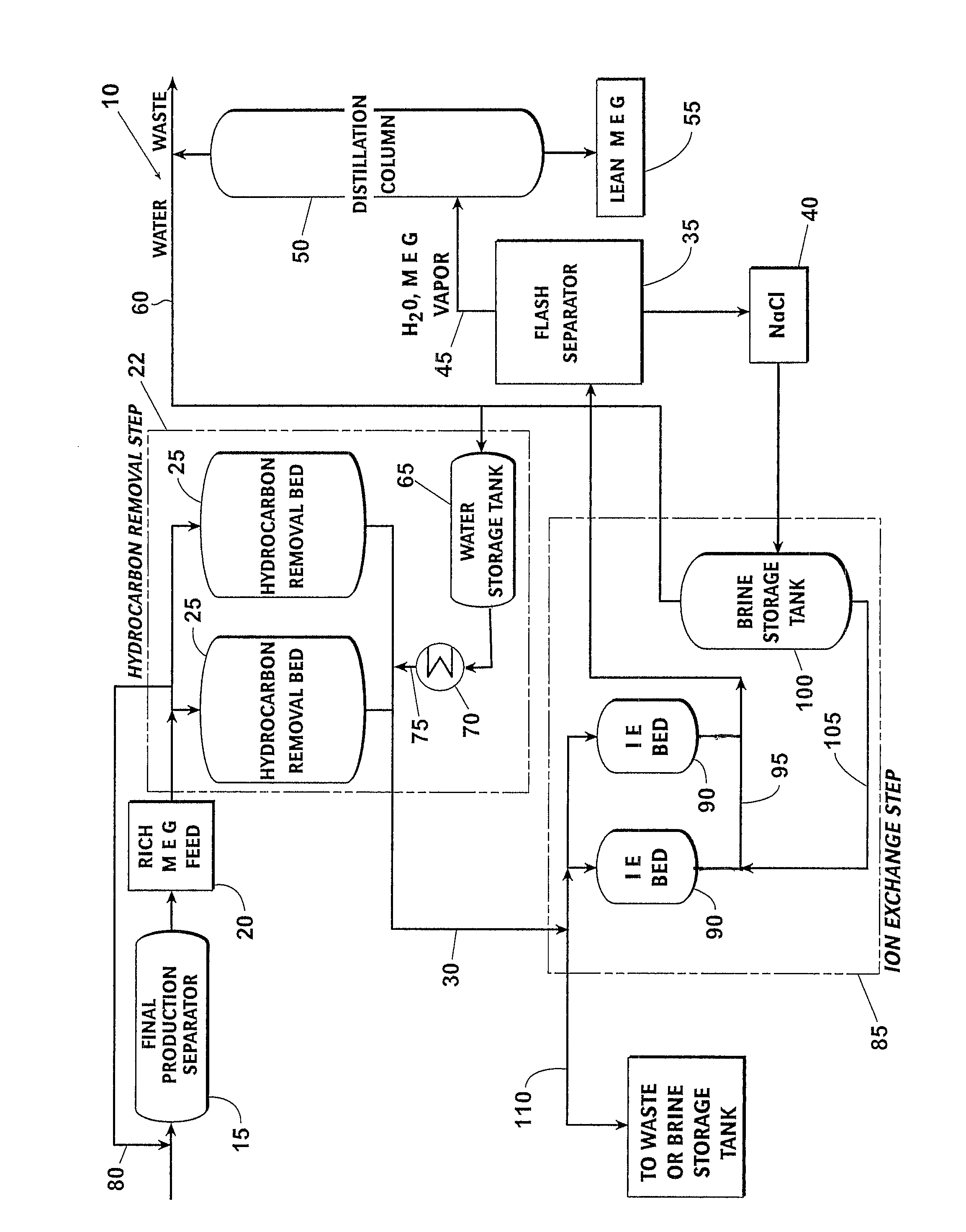
[0035]In order to maximize the recovery of lean MEG, both hydrocarbons and divalent cations should be removed from the rich MEG feed stream before the MEG reclamation process begins. Because hydrocarbons in the feed stream may interfere with the ion exchange process by coating the ion exchange resin, the hydrocarbon removal step generally occurs before the ion exchange step.

[0036]As shown in the FIGURE, a preferred embodiment of a hydrocarbon and divalent cation removal process 10 practiced according to this invention begins with the final production separator 15, which produces a mixture of produced water and MEG commonly referred to as rich MEG. The rich MEG feed stream 20 is routed to a hydrocarbon removal step 22 comprised of dual hydrocarbon removal beds 25 which contain solid adsorbent material and alternate between adsorption and regeneration phases. Suitable adsorbent materials include, but are not limited to, DOWEX OPTIPORE® (Dow Chemical Co., Midland, Mich.). In the adsorp...


PUM

PropertyMeasurementUnit
Pressureaaaaaaaaaa

Abstract

A system and process for removing hydrocarbons and divalent cations from a rich MEG feed stream is presented. A hydrocarbon removal bed containing a solid adsorbent material adsorbs the hydrocarbons in the rich MEG feed stream as it passes through the hydrocarbon removal bed. After the hydrocarbons have been removed, the rich MEG feed stream flows through an ion exchange bed containing an ion exchange resin in order to remove divalent cations. The rich MEG feed stream then flows through a flash separator and a distillation column to reclaim MEG. Spent solid adsorbent material in the hydrocarbon removal beds and spent ion exchange resin in the ion exchange beds may be regenerated in place using by-products of the MEG reclamation process.

Description

BACKGROUND[0001]Monoethylene glycol (MEG) is commonly used in the oil and gas industry to prevent the formation of gas hydrates in pipelines. The MEG is injected at the wellhead and readily mixes with the produced water to form a mixture referred to as rich MEG.[0002]The oil and rich MEG are separated in the final production separator. However, depending upon the properties of the oil, the hydrocarbon content of the rich MEG may be as high as 1,000 parts per million (ppm). When the oil properties are in the range of a light condensate, the hydrocarbon content may range from 100 ppm to 200 ppm, but even these concentrations may be excessive for optimal operation of the MEG reclamation process.[0003]Increasing the removal of hydrocarbons from the rich MEG will improve the operation of the MEG reclamation process. In addition, hydrocarbon removal eliminates or significantly reduces potential difficulties during the reclamation process. As an example, the rich MEG feed stream must be he...

Claims


Application Information

Patent Timeline
IPC IPC(8): B01D3/06C07C29/76
CPCB01D15/362C07C29/76B01D15/00C07C31/202
Inventor PHELPS, DANIEL W.FERNANDEZ, LUIS EDUARDO CAIRES
Owner CAMERSON INT CORP
Why Eureka
Try Eureka