Determining a polarization-related characteristic of an optical link

a technology of polarization and optical path, applied in the field of measuring polarization-related characteristics of optical paths, can solve the problems of limiting the bandwidth of a single optical channel along a “long-haul” (i.e. long-distance) optical link, signal sop at the fiber input is not well controlled, and documentation of these measurements may have been lost or misplaced

Active Publication Date: 2014-03-13
EXFO
View PDF4 Cites 39 Cited by
  • Summary
  • Abstract
  • Description
  • Claims
  • Application Information

AI Technical Summary

Benefits of technology

[0052]The present invention seeks to eliminate, or at least mitigate, the disadvantages of the prior art discussed above, or at least provide an alternative.

Problems solved by technology

In other words, PMD may be the primary impairment limiting the reach (i.e. maximum propagation distance) of high bit- / symbol-rate signals, and PMD may limit the bandwidth that may be carried in a single optical channel along a “long-haul” (i.e. long-distance) optical link.
In general, however, the signal SOP at the fiber input is not well controlled (and often may change unpredictably over time), and consequently the level of signal DGD at a particular wavelength is less than the corresponding DGD at that same wavelength.
If measurements of the link PMD had been taken at some earlier date (e.g. during installation of the fiber plant), the documentation of these measurements may have been lost or misplaced, for instance following acquisition of existing fiber plant purchased from a third party.
Furthermore, PMD values taken several years earlier may no longer be indicative of current PMD behavior, due to fiber ageing, etc.
Obviously, the launch of a continuous spectrum of broadband light from a test source would likely disrupt network operations and, hence, would be incompatible with the concurrent transmission of active data-carrying signals in the same FUT.
However, there are significant additional operational costs involved with placing a dedicated source at one end and the measurement equipment at the other, in addition to the difficulties often associated with providing regular communication between the equipment placed at the opposing ends.
As explained in commonly-owned U.S. Pat. No. 6,724,469 (Leblanc), in optical communication systems, an unacceptable overall polarization mode dispersion (PMD) level for a particular long optical fiber may be caused by one or more short sections of the optical fiber link.
Accordingly, Leblanc discloses a method of measuring distributed PMD which uses a polarization OTDR, to identify high or low PMD fiber sections, but does not provide a truly quantitative PMD value for the FUT.
Consequently, because of its inherently “qualitative” nature, Leblanc's technique is not entirely suitable for development as a commercial single-ended overall PMD testing instrument that may measure the total PMD value for the entire of fiber link.

Method used


Image

  • Determining a polarization-related characteristic of an optical link
  • Determining a polarization-related characteristic of an optical link
  • Determining a polarization-related characteristic of an optical link

Examples


embodiment (

1)—Two-Ended “Test-Source-Based” DGD and / or PMD Measurement

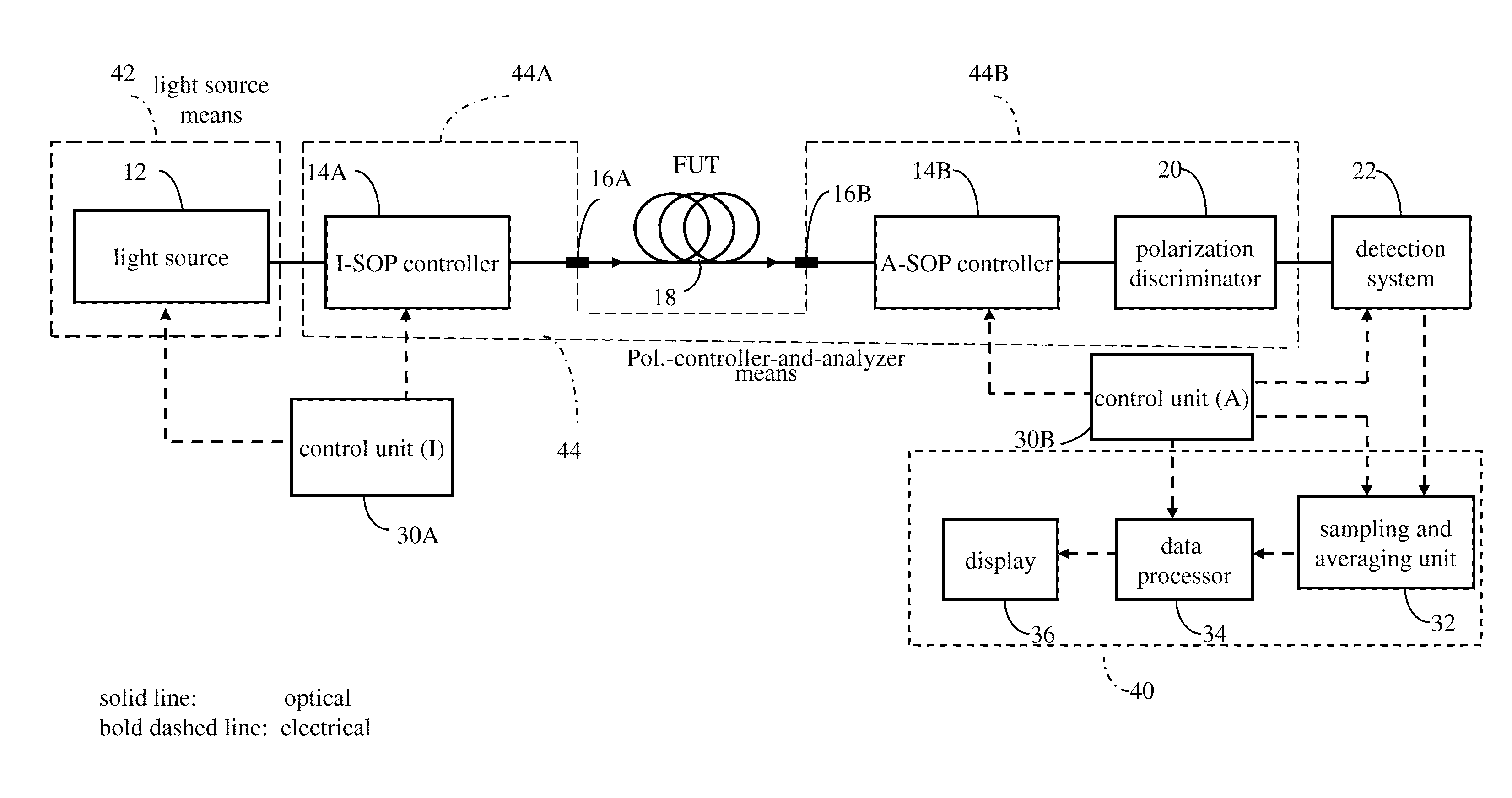
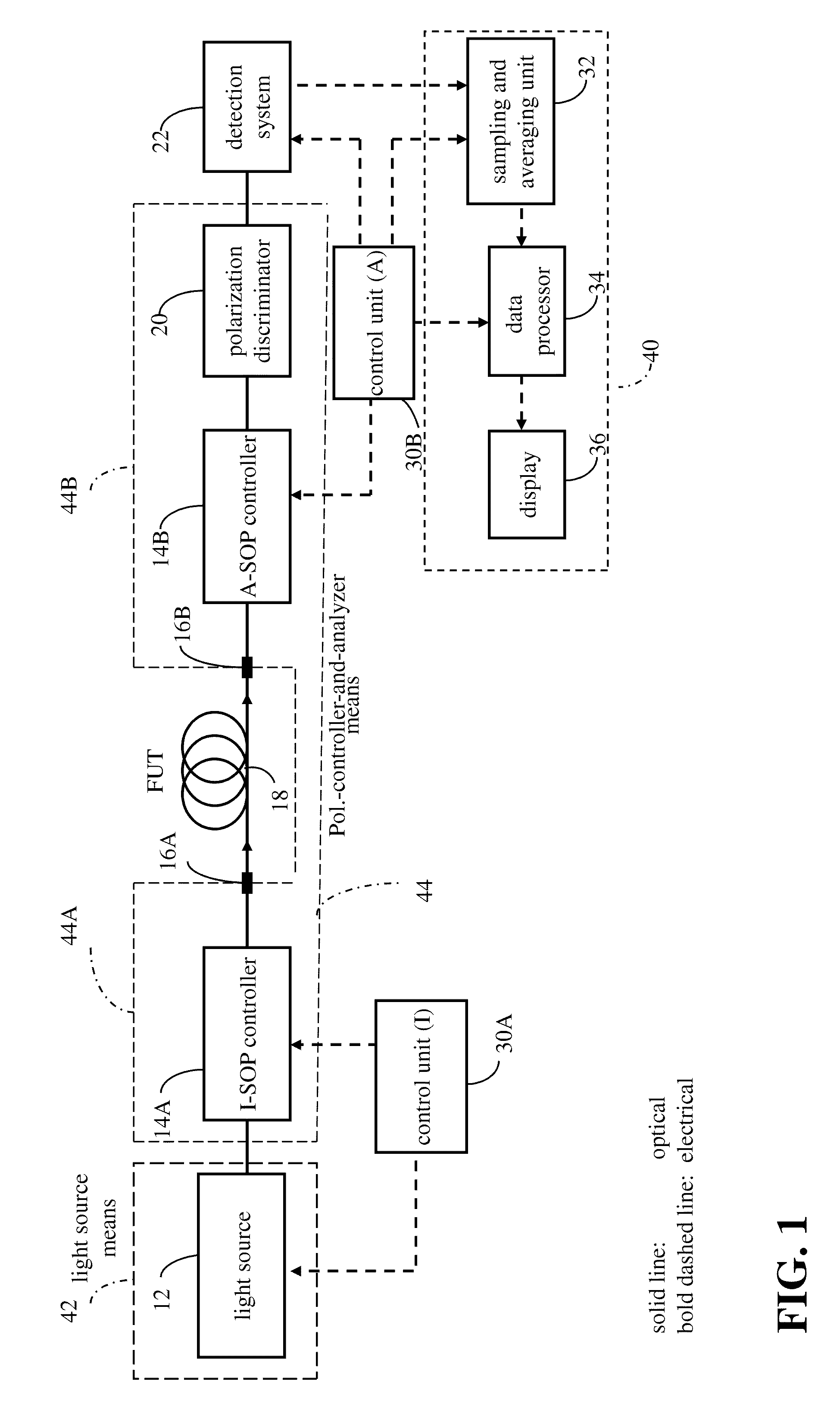
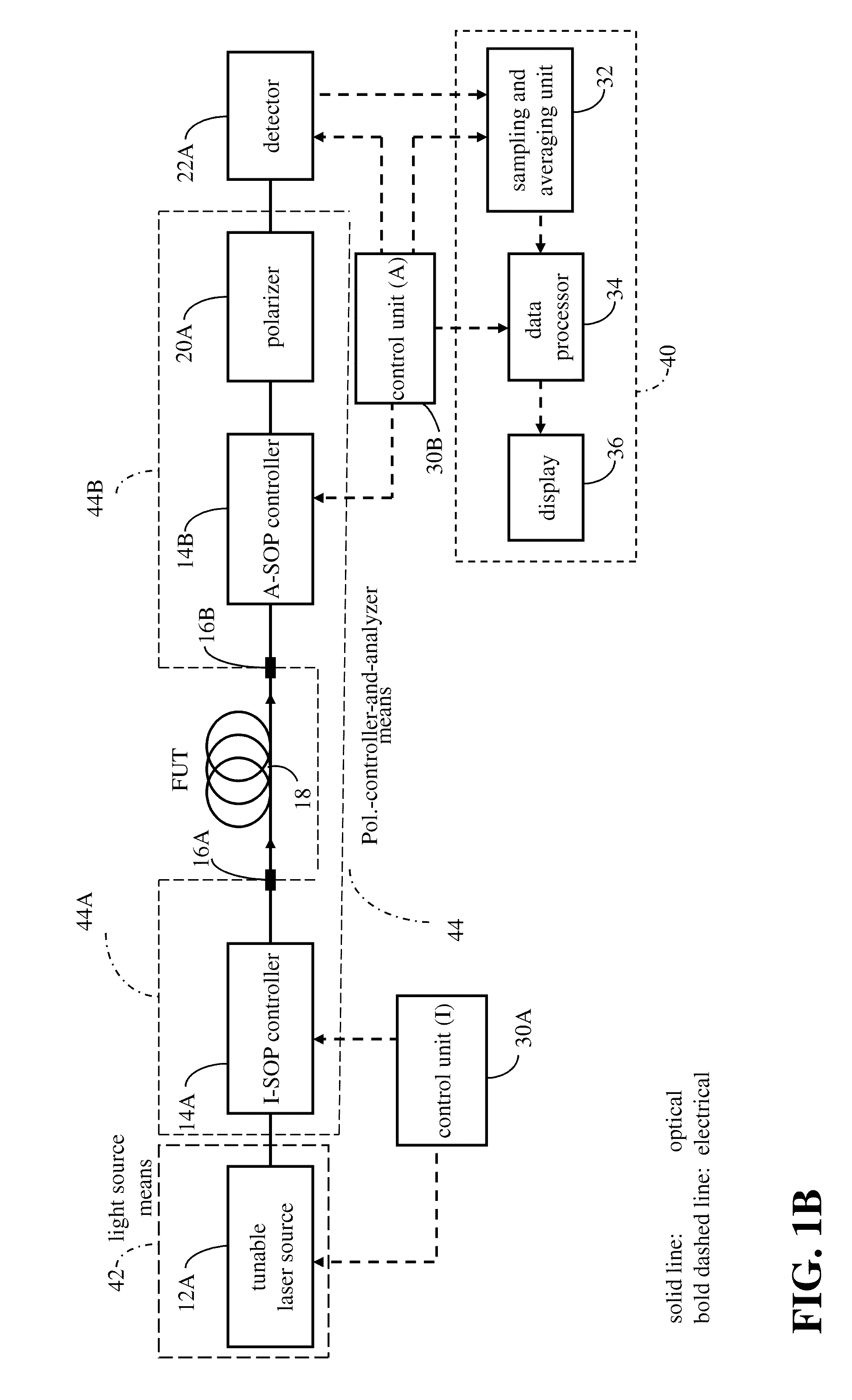
[0431]The method of operation for a measurement instrument of Embodiment (1) (“two-ended PMD measurement) for measurement of DGD and / or PMD, as shown generically in FIG. 1, will now be described in more detail with reference to the flowcharts shown in FIGS. 5A, 5B, 5C and 5D.

[0432]In steps 4.1 and 4.2, the user first installs the application and, if applicable, inserts the test modules in the platforms. Then the user starts testing software to cause the system to initialize the test modules, specifically initializing the wavelength of the polarized light source 12 (either tunable laser source 12A or broadband light source 12B), the Input SOP controller (I-SOP) 14A, the analyzing means 14B and 20 and the detection 22 and processing section 34. Then the one end of fiber under test (FUT) 18 is connected to source module before I-SOP 14A and the distal end of FUT 18 are connected to analyzer-and-detection module, and patch cords...


PUM

PropertyMeasurementUnit
optical-frequencyaaaaaaaaaa
lengthaaaaaaaaaa
wavelength rangeaaaaaaaaaa

Abstract

A polarization-related characteristic of an optical path is determined from a predetermined function of the mean-square of a plurality of differences between polarization-analyzed optical power parameters corresponding to pairs of wavelengths mutually spaced about a midpoint wavelength by a small optical frequency difference. At least some of the said differences correspond to wavelength pairs measured under conditions where at least one of midpoint wavelength, input state of polarization (I-SOP) or analyzed state of polarization (A-SOP) of a pair is different.

Description

CROSS-REFERENCE TO RELATED DOCUMENTS[0001]This application is a Continuation-in-Part of U.S. patent application Ser. No. 12 / 568,554 filed Sep. 28, 2009, published as United States Patent Publication number US2010 / 0073667 A1 claiming priority from U.S. Provisional patent application No. 60 / 907,313 filed 28 Mar. 2007 and also a Continuation-in-Part of U.S. patent application Ser. No. 11 / 727,759 filed 28 Mar. 2007, now abandoned, and a Continuation-in-Part of U.S. patent application Ser. No. 11 / 992,797 having an effective filing date Mar. 28, 2008. The entire contents of each of these patent documents are incorporated herein by reference and the reader is directed to them for further reference.TECHNICAL FIELD[0002]This invention relates to a method and system for measuring polarization-related characteristics of optical paths, which may lead to impairments of a data-carrying signal propagating therealong. The optical path normally comprises mostly optical waveguide, such as an optical ...

Claims


Application Information

Patent Timeline
Patent Type & Authority Applications(United States)
IPC IPC(8): G01N21/21G06F17/18
CPCG06F17/18G01N21/21G01M11/3163G01M11/3181G01M11/336G01M11/335
Inventor CYR, NORMANDCHEN, HONGXINSCHINN, GREGORY WALTET
Owner EXFO
Why Eureka
Try Eureka