System for determining the topography of the cornea of an eye

a topography and eye technology, applied in the field of eye topography determination system, can solve the problems of difficult illumination, interference with detection, and difficult to measure the surface of the cornea of the human eye, and achieve the effect of more cost-effective and high light efficiency

Active Publication Date: 2014-03-20
CARL ZEISS MEDITEC AG
View PDF3 Cites 15 Cited by
  • Summary
  • Abstract
  • Description
  • Claims
  • Application Information

AI Technical Summary

Benefits of technology

[0038]The underlying object of the present invention is to develop a system for determining the topography of the cornea of an eye, which system permits largely distance-independent measurements in a fairly large measuring area and given severe asphericity permits and generates for it a plurality of measurement points. A technical embodiment that has higher light efficiency and thus may be produced in a much simpler manner, and thus more cost effectively, shall be used for illumination.

Problems solved by technology

Measuring the surface of the cornea of the human eye proves to be difficult because the cornea is transparent and no significant amount of visible light is backscattered.
Due to the disk-shaped structure, the number of realizable rings is limited, and in addition this type of illumination is very difficult to achieve as the number of rings increases.
One drawback of this type of solution is that the images captured by the camera include an image of the eye, in particular its iris and the parasitic image of the Placido rings projected onto the tear film in front of the cornea as an overlay.
The problem that may occur is that the overlaid iris structure may interfere with detection of the Placido rings because in some circumstances the edge of the pupil can be confused with the rings.
A second drawback of such solutions is that the accuracy of the measurement is highly dependent on the angular ratios and thus on the measurement distance.
Although this method provides precise, reliable, and reproducible results for the majority of eyes to be examined, i.e. eyes with “normal” curvatures of the cornea, problems may occur when there “abnormal” curvatures of the cornea.
However, these algorithms combine the measurement inaccuracies for all rings due to error propagation and the results are thus inaccurate depending on data quality.
In patients with healthy cornea shapes this problem may be overcome using very high measuring quality, but very major measurement deviations may occur with corneas that are abnormally deformed.
However, Helmholz's keratometer was very unwieldy.
However, the low number of measuring points in Littmann keratometers proved to be a drawback.
It is a drawback of this method that the cornea is measured at only a few points and thus there may be measurement errors, in particular for corneas that have additional surface deformations in addition to curvature and astigmatism.
However, since a separate source with imaging optics is necessary for each measuring point, the technical complexity is that much greater.
A drawback of this method is the relatively high technical complexity for this imaging optics unit, since a plurality of lenses must be employed to attain the required high accuracy and to be able to compensate spherical errors that occur.
Another drawback is the low light efficiency that results from the relatively narrow annular filter widths.

Method used


Image

  • System for determining the topography of the cornea of an eye
  • System for determining the topography of the cornea of an eye
  • System for determining the topography of the cornea of an eye

Examples


second embodiment

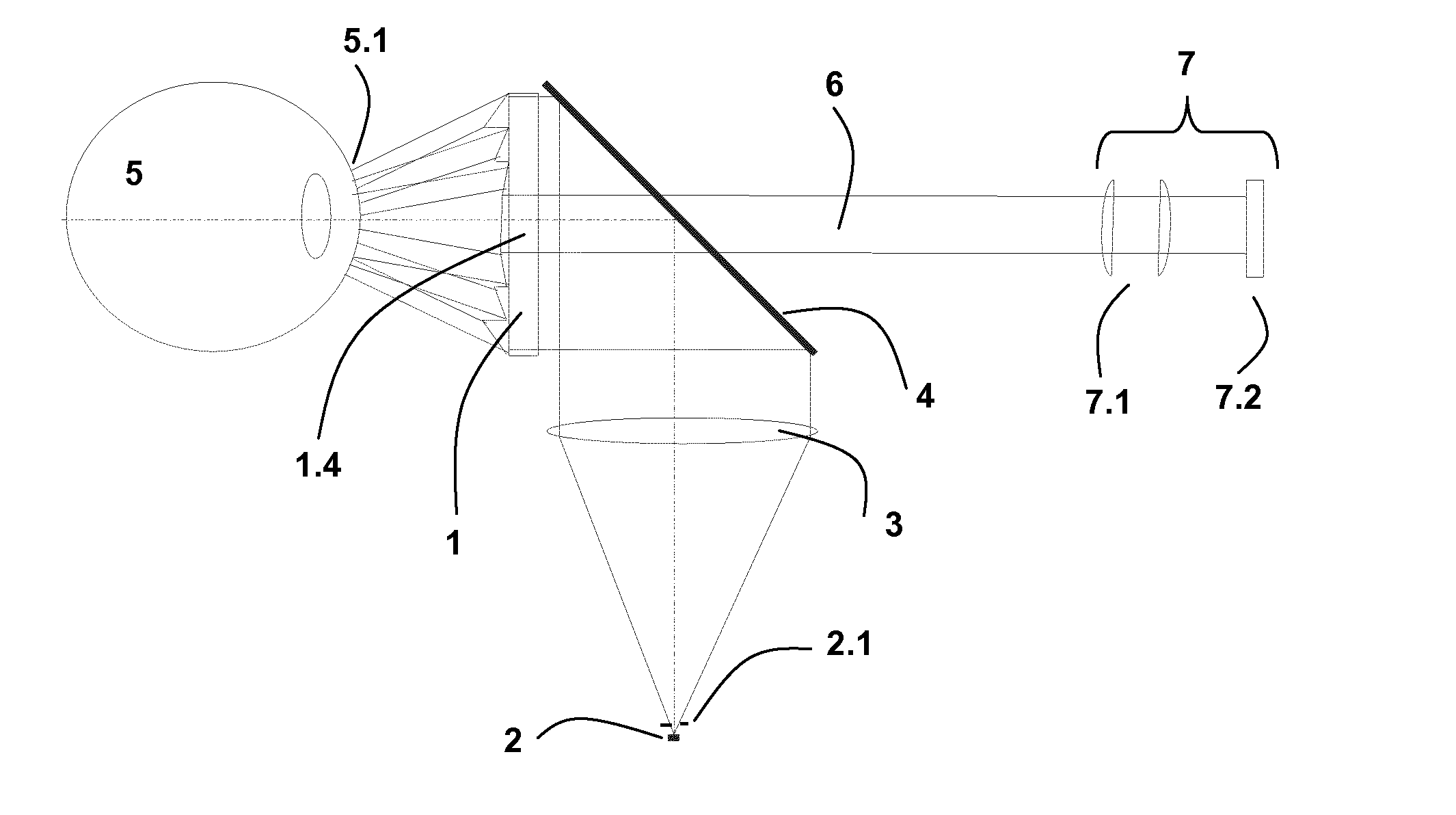
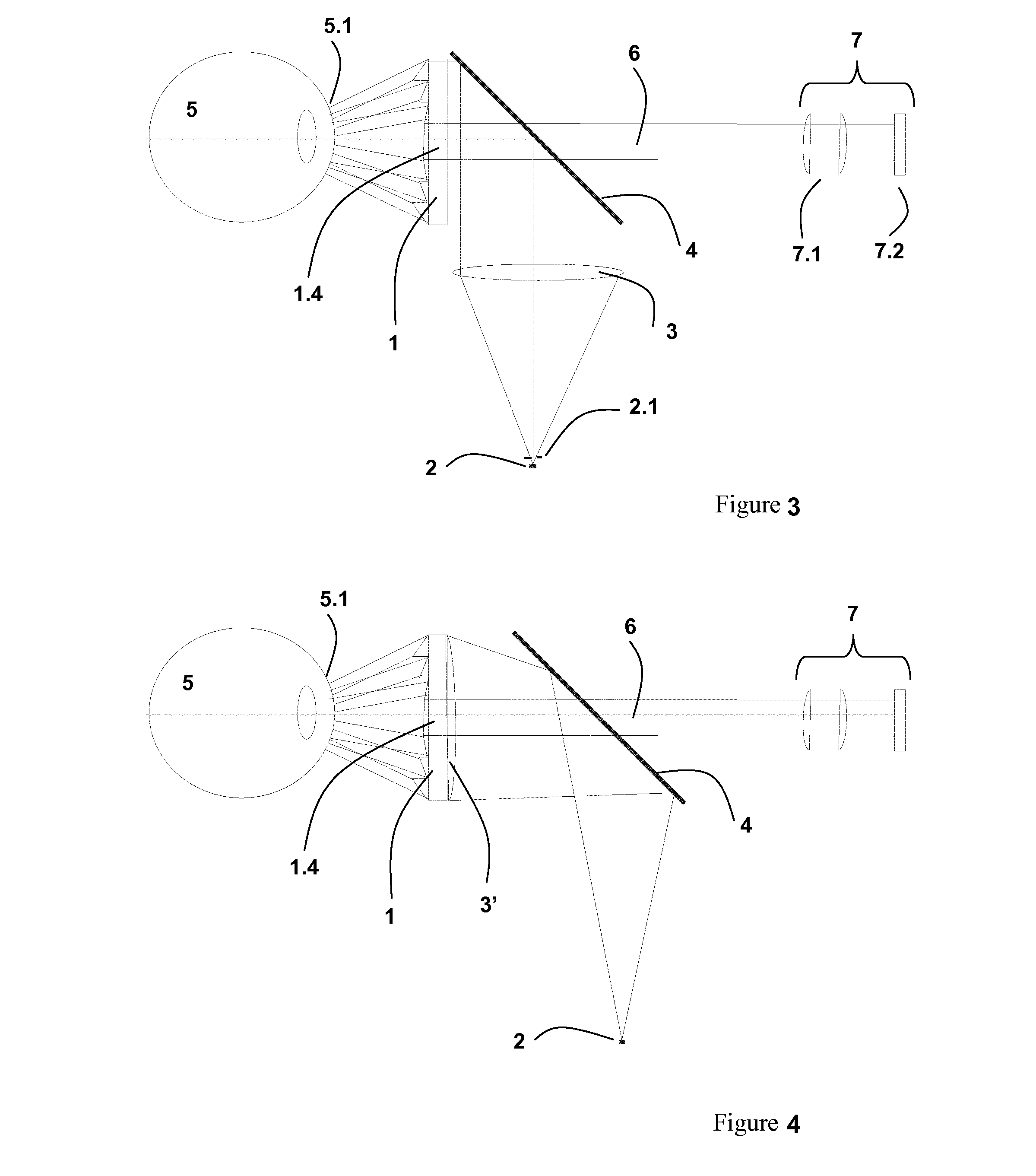
[0074]In one example embodiment, the collimator lens normally used as the optical element for illuminating the entire surface of the fresneled axicon may be omitted if the back side of the fresneled axicon is embodied appropriately. In this regard, FIG. 4 is a schematic diagram of the inventive system having only one beam splitter.

[0075]In this case, the light emitted by an LED 2 is deflected towards the fresneled axicon 1 by a beam splitter in the form of a partially silvered plane-parallel plate 4. The back side 1.2 of the fresneled axicon 1 that is embodied as a collimator lens 3′ parallelizes the light for illuminating the entire surface so that there is no need for a separate optical element. The partial silvering of the plane-parallel plate 4 may then be embodied such that its center does not have any silvering so that illumination of the central zone 1.4 of the fresneled axicon 1 is avoided. The light of the LED 2 at different angles is reproduced on the cornea 5.1 of the eye...

first embodiment

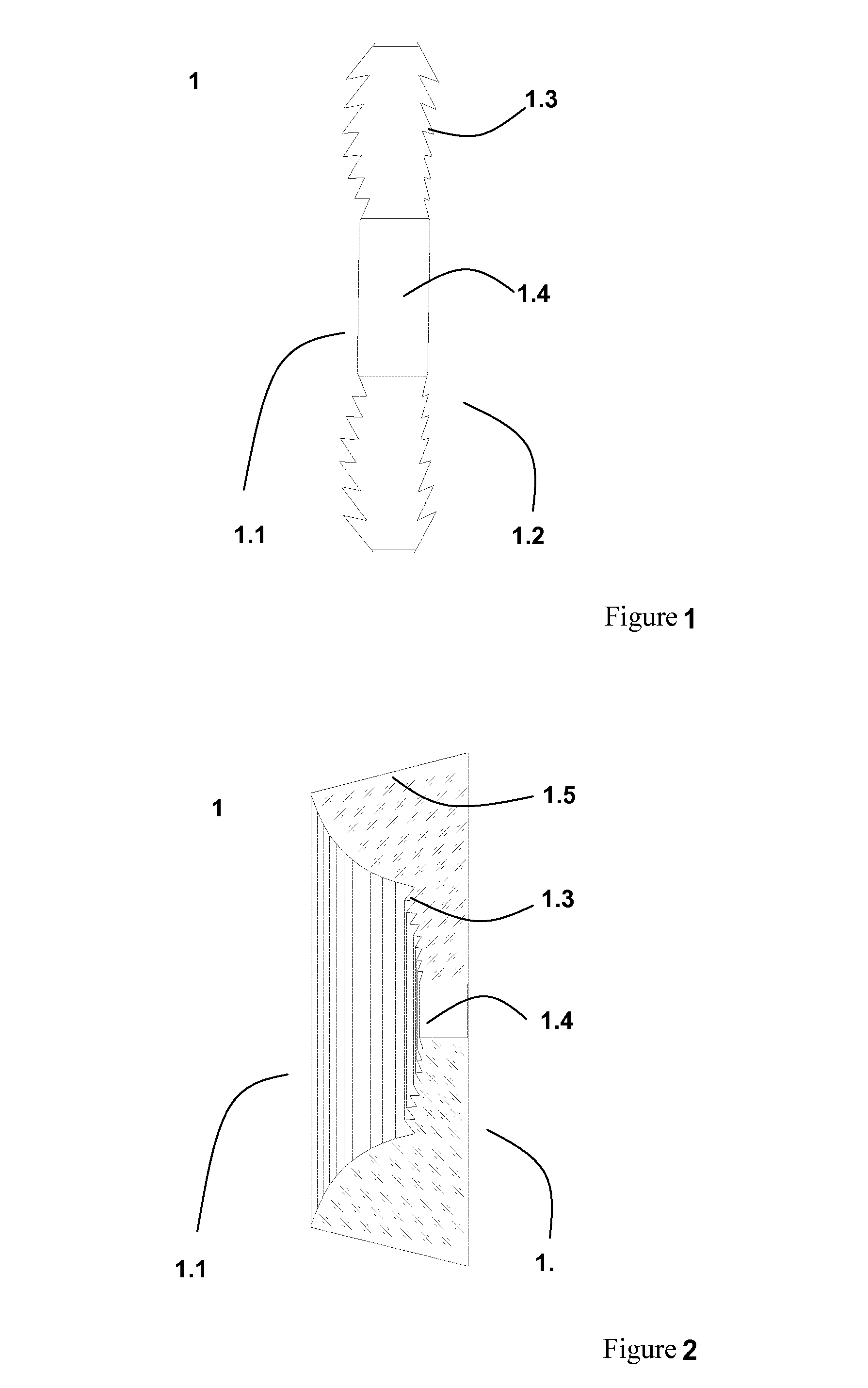
[0106]In a first embodiment, one of the two optically active surfaces of the fresneled axicon also has a diffractive structure in the form of a diffraction grid, the grid lines of which run radially and the grid vectors of which run azimuthally on each location. In one further example embodiment, diffraction grids are used that have different local frequencies.

[0107]In a second example embodiment, one of the two optically active surfaces of the fresneled axicon also has a sinusoidal structure that runs radially. The modulation depth of the sinusoidal structure is between a few μm and a few 100 μm and its wavelength is between 0.1 mm and 20 mm. For example, the wavelength is approximately 2 mm.

[0108]The essential feature of this second example embodiment is that due to the azimuthal structures, in each section the partial waves remain completely collimated by the optical axis, while in the plane perpendicular thereto they are not focused in a sphere onto the optical axis. The wave ma...


PUM


Abstract

A system for determining the surface shape of the cornea of an eye by analyzing the reflection of a spatially distributed ring pattern. The system includes an element for generating a ring pattern, an illuminating unit, an image capturing unit, and a control and analyzing unit. The element for generating rings is a fresneled axicon with annular structures of different radii. Furthermore, an optical element for illuminating the entire surface of the fresneled axicon with plane waves and an optical element for separating the illuminating and detecting beam path are arranged between the illuminating unit and the fresneled axicon. Furthermore, the image capturing unit consisting of an imaging system and an image sensor is designed for a telecentric distance-independent image detection.

Description

RELATED APPLICATIONS[0001]The present application is a National Phase entry of PCT Application No. PCT / EP2012 / 059458, filed May 22, 2012, which claims priority from DE Application No. 10 2011 102 355.4, filed May 24, 2011, which applications are hereby incorporated by reference herein in their entirety.FIELD OF THE INVENTION[0002]The present invention relates to a system of determining the surface shape of the cornea of an eye by analyzing the reflection of a spatially distributed pattern, especially a ring pattern similar to a Placido disk.[0003]The Placido disk is an illuminated disk that generates a known pattern in the form of circles at regular intervals and is reproduced on the eye. Diagnosis is then made by viewing the reflection of the circles on the surface of the cornea, on which the circles should be reproduced with the same regularity.[0004]Now a symmetrical reflection of the concentric Placido rings should be visible on the corneal surface. If there are rings with an as...

Claims


Application Information

Patent Timeline
Patent Type & Authority Applications(United States)
IPC IPC(8): A61B3/107
CPCA61B3/107G01B11/2513
Inventor BUBLITZ, DANIELRUDOLPH, GUNTERHACKER, MARTINBUHREN, TOBIASBERGNER, ROLANDWAGNER, BURKHARDFUCHS, RICO
Owner CARL ZEISS MEDITEC AG
Why Eureka
Try Eureka