Circuit breakers

a circuit breaker and circuit technology, applied in the field of circuit breakers, can solve the problems of affecting the performance of hvdc line insulation, affecting the reliability of hvdc transmission networks, etc., and achieves the effect of enhancing the mechanisms that are inherent, and reducing the risk of arc energy loss

Active Publication Date: 2014-03-20
GE ENERGY POWER CONVERSION TECH
View PDF2 Cites 47 Cited by
  • Summary
  • Abstract
  • Description
  • Claims
  • Application Information

AI Technical Summary

Benefits of technology

[0025]Explosion pot oil circuit breakers enhance the mechanisms that are inherent in the bulk oil circuit breaker by confining the arc within a pressure resistant electrically insulating chamber with transverse exhaust ports that are located close to the arcing space. The thermal decomposition and pressurisation of the oil causes the same turbulent fluid mixture as above to be rapidly blown through the arc and out of the exhaust. Hence the enhancement over the bulk oil circuit breaker is defined by the use of thermal energy to cause directed fluid motion. The fluid flow is highly dependent upon arc energy and low current arc interruptio

Problems solved by technology

Second, by using heating, ventilation, and air conditioning (HVAC) switchgear to interrupt the ac supply to the LCC rectifier.
An additional aspect of such voltage reversals is that the HVDC line insulation performance is adversely affected by voltage reversals and all known line insulation systems that are compatible with such voltage reversals are subject to cost and/or size penalties.
However, given the inability of known VSC topologies to limit and interrupt rectifying mode dc link current, and also given the non-availability of circuit breaker switch contact systems that can interrupt high levels of direct current and then immediately withstand a high re-applied high dc voltage between contacts, all terminals of such multi-terminal HVDC transmission networks would suffer a discontinuity of power flow while several steps take place.
Accordingly, many methods of overcoming this obstacle, i.e. satisfying the requirement to interrupt current in HVDC circuits, have been proposed but none have yet reached practi

Method used


Image

  • Circuit breakers
  • Circuit breakers
  • Circuit breakers

Examples


Embodiment Construction

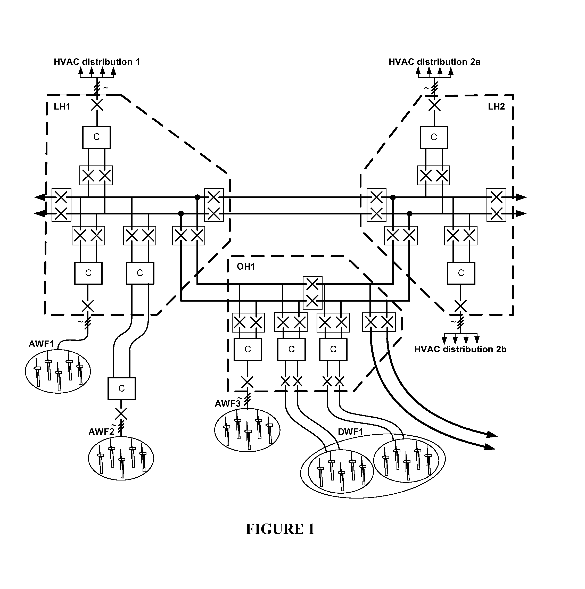
[0059]FIG. 1 shows part of a generic symmetrical bipole, multi-terminal network with meshed, point-to-point and multi-channel transmission line elements. High voltage alternating current (HVAC) circuits are identified by the industry standard symbol / / / denoting three phase circuits, but it will be readily appreciated that any convenient number of phases can be used in practice. High voltage direct current (HVDC) circuits are identified by parallel running pairs of lines. Bold lines indicate meshed heavy current circuits into which lower current circuits are terminated. The meshed heavy current circuits have a plurality of terminals (i.e. connections to the lower current circuits) and so the network defines a multi-terminal network. Such a multi-terminal network might be extensive and so only part is shown in FIG. 1 for the purpose of providing technical background to the present invention. The arrow heads provided on some of the lines indicate that the network can be extended to ot...


PUM


Abstract

A circuit breaker comprising a first dc line electrically connectable to first incoming and first outgoing dc lines, wherein the first dc line comprises a first fault-interrupting switch contact system and a first switching aid network. The first switching aid network comprises first and second rectifier strings, wherein each rectifier string comprises one or more series connected reverse blocking power electronic devices that define a first H-bridge rectifier. The first switching aid network further comprises a snubber string, the snubber string comprising at least one series connected power electronic devices capable of being turned on by gate control and a capacitor. The first switching aid network further comprises a pre-charge string comprising at least one series connected power electronic devices capable of being turned on by gate control and a resistor, and a surge arrester connected between the first and second dc output terminals of the first H-bridge rectifier.

Description

TECHNICAL FIELD[0001]The present invention relates to circuit breakers, and in particular to high voltage direct current (HVDC) circuit breakers or switchgear that can be used in point-to-point and multi-terminal HVDC power collection, transmission and distribution networks.BACKGROUND OF THE INVENTION[0002]At present, there are no known circuit breaker switch contact systems that can interrupt high levels of direct current and then immediately withstand a high re-applied high dc voltage between contacts. It is known for circuit breaker switch contact systems to be able to carry high levels of direct current and to be able to block high direct current (dc) voltage but not for such circuit breaker switch contact systems to transit from the former to the latter state.[0003]Line commutated static power converter (LCC) based HVDC transmission networks are known and any requirement to interrupt direct current in the HVDC transmission line under normal load and fault current circumstances ...

Claims


Application Information

Patent Timeline
IPC IPC(8): H01H33/59
CPCH01H33/596H02H3/087
Inventor CRANE, ALLAN
Owner GE ENERGY POWER CONVERSION TECH
Why Eureka
Try Eureka