Supercharge Your Innovation With Domain-Expert AI Agents!

Electrode assembly having novel structure and secondary battery using the same

a technology of secondary batteries and electrolyte assemblies, which is applied in the direction of non-aqueous electrolyte cells, cell components, sustainable manufacturing/processing, etc., can solve the problems of inevitably occurring contraction of generally used stretching separators, low energy density of materials for enhancing safety, and insufficient fundamentally addressing safety problems

Active Publication Date: 2014-04-03
LG ENERGY SOLUTION LTD
View PDF4 Cites 6 Cited by
  • Summary
  • Abstract
  • Description
  • Claims
  • Application Information

AI Technical Summary

Benefits of technology

The present invention is about an integrated electrode assembly that uses a separation layer with a multilayer structure including a two-phase electrolyte and a three-phase electrolyte. The separation layer prevents short-circuiting and improves the wetting properties of the electrode, which results in enhanced ionic conductivity. This is achieved by partially introducing the liquid phase components of the separation layer into the electrode during the manufacturing process, which also facilitates the impregnation of the electrode. The technical effect is to provide a secondary battery with excellent manufacturing efficiency.

Problems solved by technology

However, to use lithium secondary batteries as high-capacity power sources, many challenges that need to be addressed remain, and the most important challenge is improvement in energy density and safety.
In addition, uniformity of wetting due to large-scale area and reduction in manufacturing time are also one of the most important challenges to be addressed.
However, such materials for enhancing safety fundamentally have low energy density and do not fundamentally address problems in terms of safety, caused due to structures of lithium secondary batteries.
In these various safety problems, temperature increases when problems occur and, in this case, contraction of generally used stretching separators inevitably occurs.
Therefore, many researchers have proposed all solid type batteries to address safety problems, but such batteries cannot replace commercially available batteries due to several problems thereof.
First, currently used electrode active materials are in a solid state and, when a solid electrolyte or a polymer electrolyte is used, a contact surface between the solid electrolyte or the polymer electrolyte and the electrode active material for migration of lithium is very small.
Second, for such reason, ionic conductivity occurring at an interface between solids or an interface between a solid and a polymer is inevitably further reduced.
Third, adhesive strength is important in manufacture of a battery and, even if a solid electrolyte with high conductivity is used, it is necessary to use a polymer binder, which causes further reduction in ionic conductivity.

Method used


Image

  • Electrode assembly having novel structure and secondary battery using the same
  • Electrode assembly having novel structure and secondary battery using the same
  • Electrode assembly having novel structure and secondary battery using the same

Examples


example 1

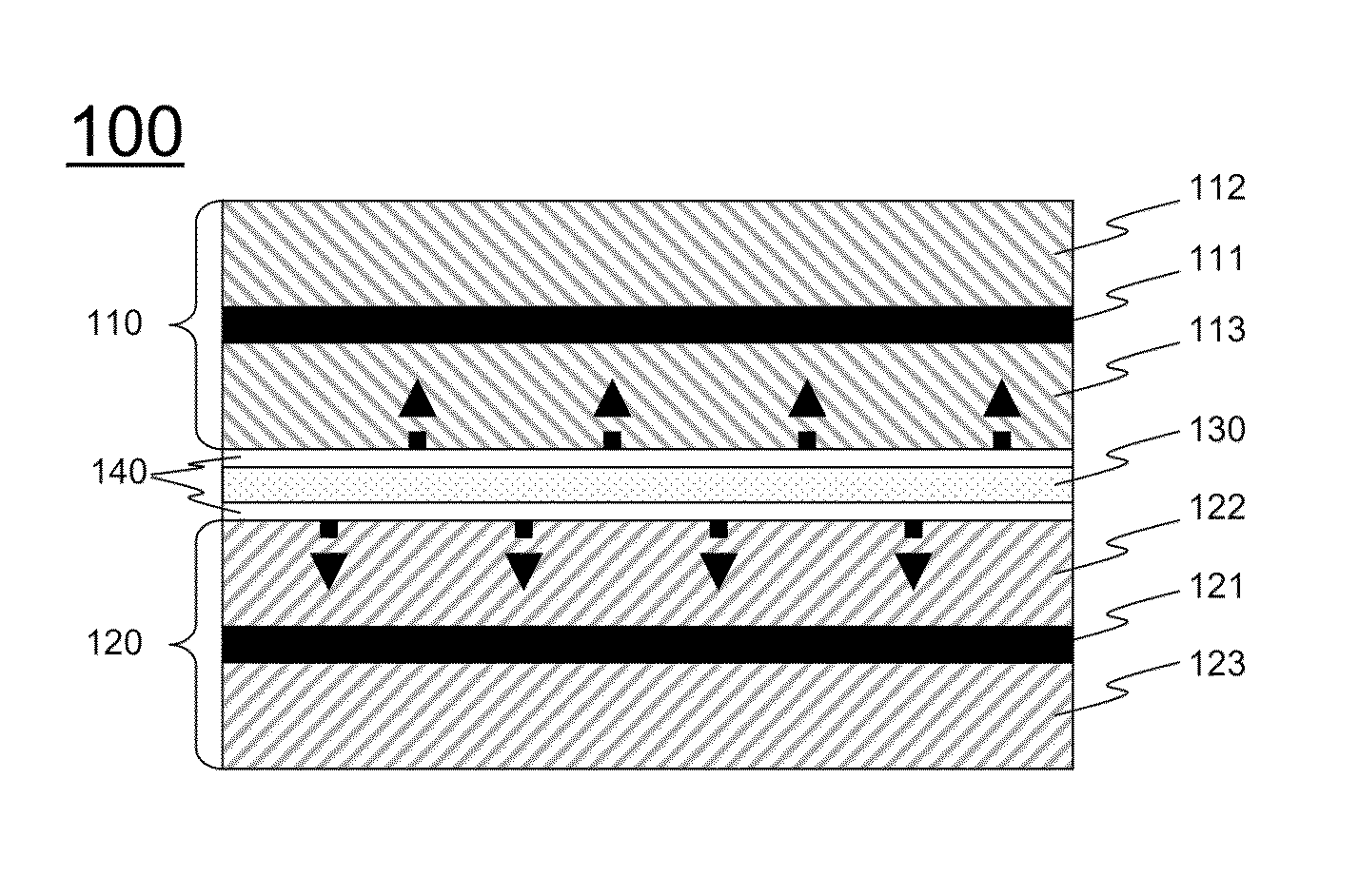
[0086]An anode was fabricated by coating a Cu foil with a slurry prepared by adding graphite, PVdF, and carbon black to NMP and drying the coated Cu foil at about 130° C. for 2 hours. A cathode was fabricated by coating an Al foil with a slurry prepared by adding LiNiMnCoO2 / LiMnO2, PVdF, and carbon black to NMP and drying the coated Al foil at about 130° C. for 2 hours.

[0087]A two-phase electrolyte layer and a three-phase electrolyte layer were prepared so as to have composition ratios shown in Table 1 below, and benzoin, which is a UV initiator, was added in an amount of 3 wt % based on the amount of PEGDMA.

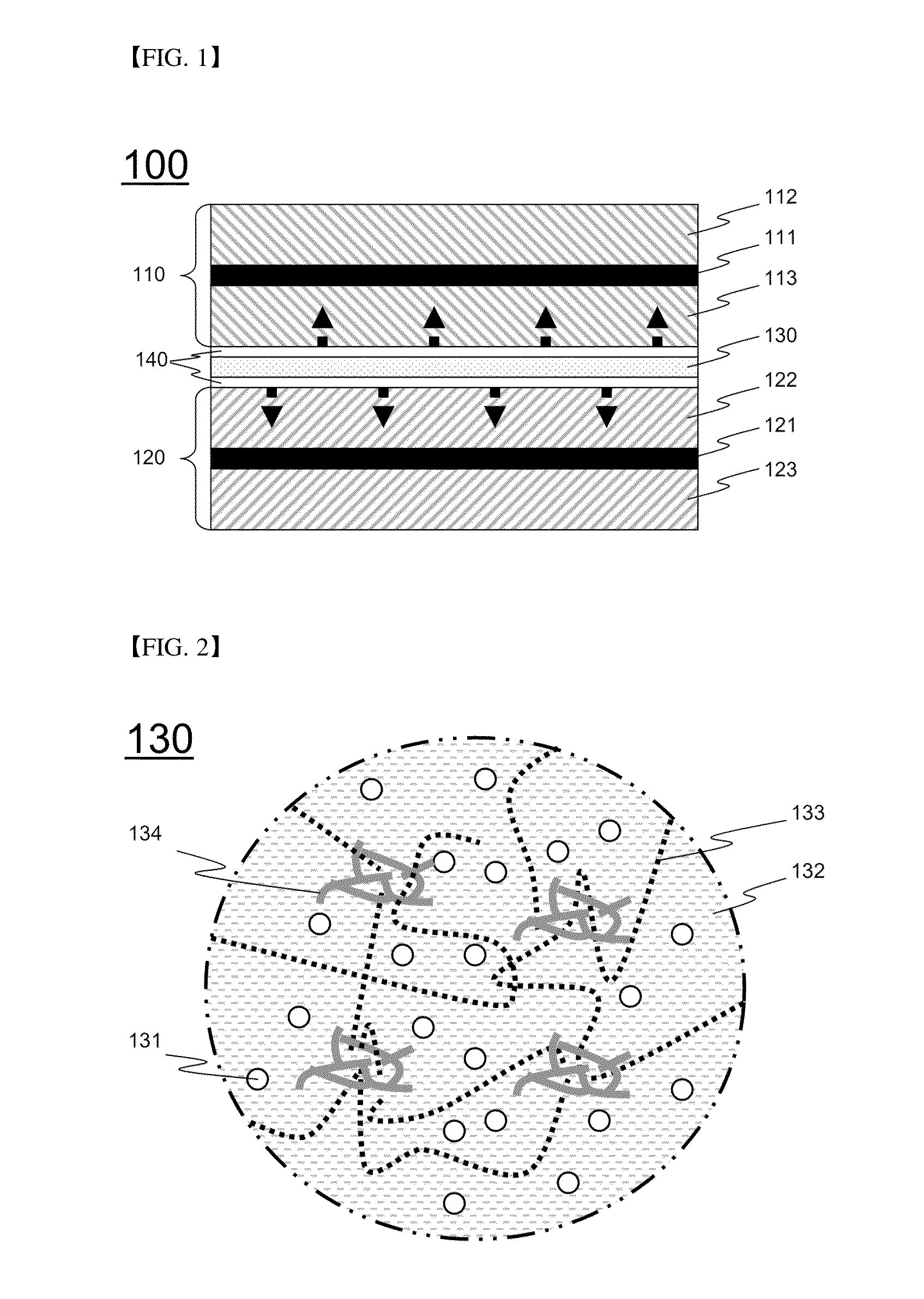
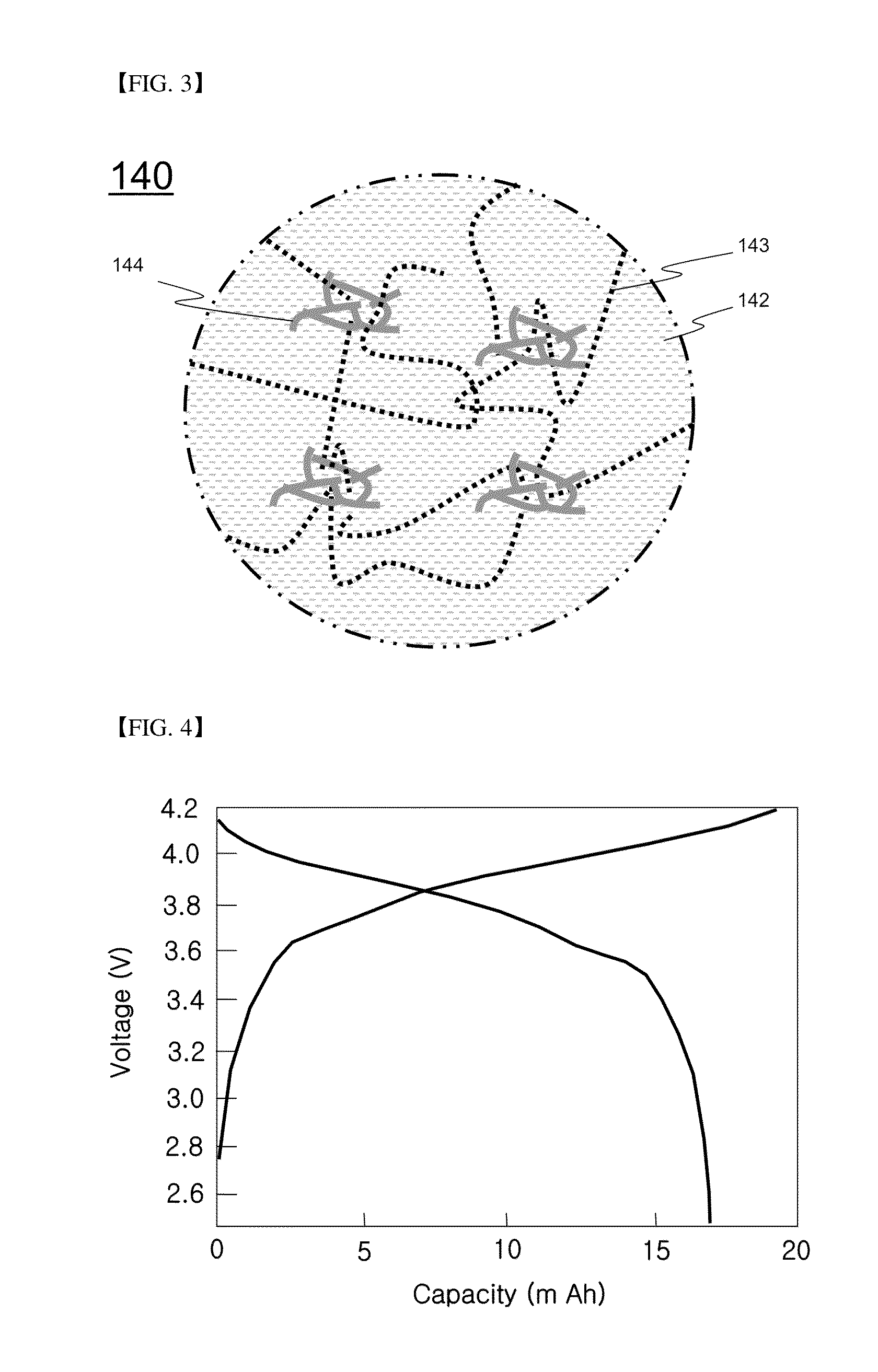
TABLE 1Organic electrolyte solution(1M LiPF6, EC / DEC = 1 / 1)PEOPEGDMASiO2Two-phase502525—electrolyte layerThree-phase83.77.47.41.5electrolyte layer

[0088]A two-phase electrolyte was coated on surfaces of the prepared cathode and anode, followed by polymer cross-linking through UV irradiation, to form a polymer electrolyte layer having a viscoelastic structure. Thereafter, a three-...

experimental example 1

[0090]Characteristics of the secondary battery manufactured according to Example 1 were evaluated without performing a separate impregnation process.

[0091]The secondary battery of Example 1 was charged at a current density of 0.1 C and a constant current (CC) until voltage reached 4.2 V and maintained at a constant voltage (CV) of 4.2 V and, when current density reached 0.05 C, the charging process was completed. In addition, the secondary battery of Example 1 was discharged at a current density of 0.1 C and a CC until voltage reached 2.5 V. Charging and discharging cycles were repeated by 50 times under the same conditions.

[0092]A discharge profile of the secondary battery of Example 1 exhibited excellent discharge characteristics and high capacity although a separate electrolyte solution was not added and a separate impregnation process was not implemented.

[0093]A first charge-discharge profile and cycle lifespan characteristics of the secondary battery of Example 1 are shown in F...

experimental example 2

[0094]Characteristics of the secondary batteries of Example 1 and Comparative Example 1 were evaluated without separation impregnation. Discharge capacity in a first charge / discharge cycle of each secondary battery is shown in Table 2 below.

TABLE 2Capacity with respect to1st discharge capacitytheoretical capacity (17 mAh)Example 116.5 mAh97.0%Comparative15.5 mAh91.2%Example 1

[0095]Table 2 shows evaluation results of charge / discharge characteristics of the secondary batteries of Example 1 and Comparative Example 1 without performing impregnation of the electrolyte solution. From the results shown in Table 2, it can be confirmed that the secondary battery of Example 1 exhibited higher 1st discharge capacity than that of the secondary battery of Comparative Example 1 and high capacity with respect to theoretical capacity (17 mAh).


PUM

PropertyMeasurementUnit
particle diameteraaaaaaaaaa
thicknessaaaaaaaaaa
constant voltageaaaaaaaaaa

Abstract

Disclosed is an integrated electrode assembly having a structure in which a cathode, an anode, and a separation layer disposed between the cathode and the anode are integrated with one another, wherein the separation layer has a multilayer structure including at least one two-phase electrolyte including a liquid phase component and a polymer matrix and at least one three-phase electrolyte including a liquid phase component, a solid component, and a polymer matrix, wherein the polymer matrices of the separation layer are coupled to the cathode or the anode and the liquid phase components of the separation layer are partially introduced into an electrode in a process of manufacturing the electrode assembly.

Description

TECHNICAL FIELD[0001]The present invention relates to an electrode assembly having a novel structure and a secondary battery using the same. More particularly, the present invention relates to an integrated electrode assembly having a structure in which a cathode, an anode, and a separation layer disposed between the cathode and the anode are integrated with one another, wherein the separation layer has a multilayer structure including at least one two-phase electrolyte including a liquid phase component and a polymer matrix and at least one three-phase electrolyte including a liquid phase component, a solid phase component, and a polymer matrix, wherein the polymer matrices of the separation layer are coupled to the cathode or the anode and the liquid phase components of the separation layer are partially introduced into an electrode in a process of manufacturing the electrode assembly.BACKGROUND ART[0002]As energy source prices are increasing due to depletion of fossil fuels and i...

Claims


Application Information

Patent Timeline
Patent Type & Authority Applications(United States)
IPC IPC(8): H01M10/0565H01M10/04H01M10/052H01M50/414H01M50/42H01M50/426H01M50/457
CPCH01M10/0565H01M10/04H01M10/052H01M10/058H01M50/42H01M50/426H01M50/414H01M50/457H01M10/0525H01M10/0566H01M2300/0094Y10T29/49108Y02P70/50Y02E60/10H01M50/446Y02T10/70
Inventor KWON, YOHANCHANG, SUNG-KYUNHONG, SEUNG-TAEKIM, JE YOUNGKIM, SUNGJIN
Owner LG ENERGY SOLUTION LTD
Features
  • R&D
  • Intellectual Property
  • Life Sciences
  • Materials
  • Tech Scout
  • Unparalleled Data Quality
  • Higher Quality Content
  • 60% Fewer Hallucinations
Learn More