Optical fiber line characteristic analysis apparatus and analysis method thereof

a characteristic analysis and optical fiber technology, applied in the direction of optical apparatus testing, reflectometers using simulated back-scatter, instruments, etc., can solve the problems of inability to apply, inability to individually identify branched optical fibers, and inability to analyze expensively

Active Publication Date: 2014-04-10
NIPPON TELEGRAPH & TELEPHONE CORP
View PDF4 Cites 10 Cited by
  • Summary
  • Abstract
  • Description
  • Claims
  • Application Information

AI Technical Summary

Benefits of technology

[0025]As described above, the present invention utilizes the difference ΔL in length between the plurality of branched optical fibers into which the trunk optical fiber line is split at the splitting point by the optical splitter, prepares two types of test light with different wavelengths, pulses the two types of test light, applies an input time difference between the two types of pulsed test light, and inputs the resultant two types of pulsed test light to the measurement target optical fiber line. Thus, reflected light of the previously input pulsed test light (first test light beam) and the subsequently input pulsed test light (second test light beam pulse) propagate opposite each other to generate stimulated Brillouin backscattered light. Then, the optical receiver receives the stimulated Brillouin backscattered light. An output current from the optical receiver is analyzed at a time resolution of higher than 2nΔL / c (c is light speed). This enables determination of in which of a first branched optical fiber to an Nth branched optical fiber the stimulated Brillouin scattering has occurred. Consequently, a characteristic distribution can be determined for each branched optical fiber.
[0026]Thus, the present invention can provide an optical fiber line characteristic analysis apparatus and an optical fiber line characteristic analysis method which enable the characteristics of branched optical fiber lines to be individually, precisely, and inexpensively analyzed without the need to replace existing outside facilities.

Problems solved by technology

However, for the passive optical network (PON) optical split line, the optical pulse line monitoring apparatus has difficulty individually identifying branched optical fibers positioned on a user apparatus side with respect to an optical splitter or the states of an optical device (reflective filter), a splitter, a fiber connection component, and the like which are connected to the optical fiber line.
Thus, the existing optical pulse line monitoring apparatus is basically effective on a single optical fiber line and fails to be applied directly to optical split lines.
However, this technique is limited to a level at which a defective branched optical fiber line is identified and a defective position is isolated, for example, which of the user apparatus and the optical fiber line is defective is determined, and fails to determine where in the branched optical fiber the defect is occurring.
However, optical splitting devices with a wavelength routing function, typified by a wavelength multiplexer / demultiplexer of a diffraction grating type based on an array waveguide, are generally expensive.
It is difficult, in terms of costs, to use such an optical splitting device for an access network optical system accommodating a large number of subscribers.
This leads to the need for high costs when the system is constructed.

Method used


Image

  • Optical fiber line characteristic analysis apparatus and analysis method thereof
  • Optical fiber line characteristic analysis apparatus and analysis method thereof
  • Optical fiber line characteristic analysis apparatus and analysis method thereof

Examples


Embodiment Construction

[0054]An embodiment of the present invention will be described with reference to the drawings. The embodiment described below is an example of a configuration of the present invention, and the present invention is not limited to the embodiment described below.

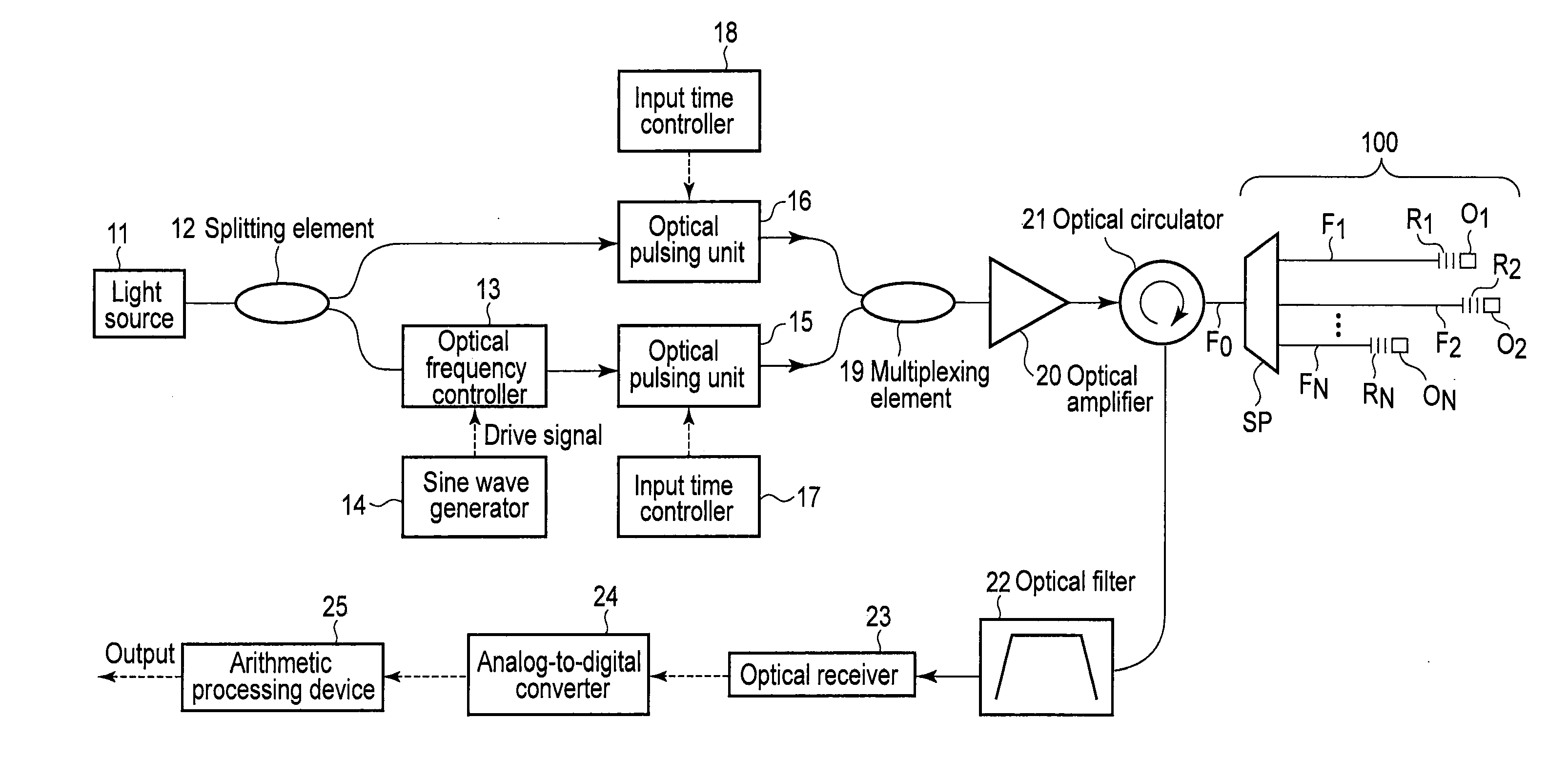
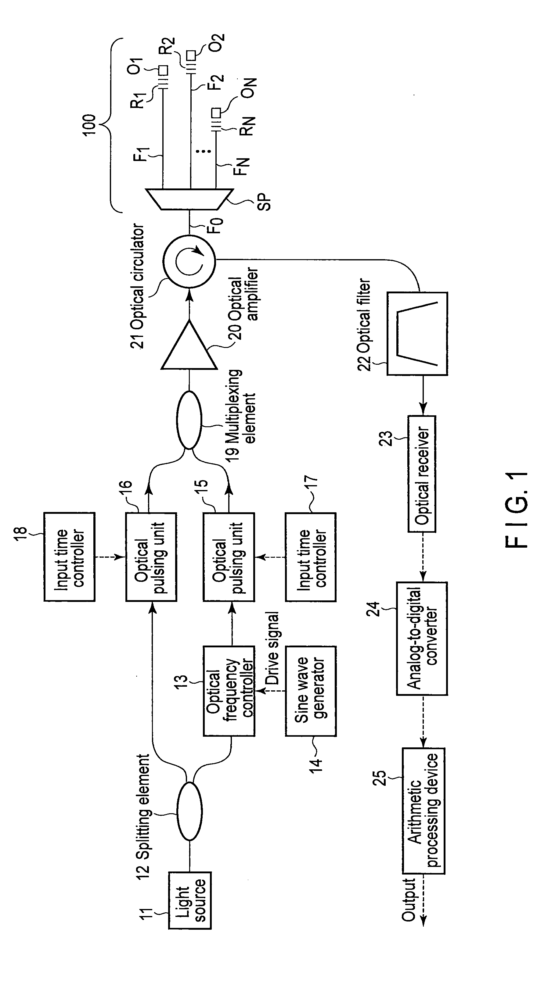
[0055]FIG. 1 is a block diagram showing a configuration of an optical fiber line characteristic analysis apparatus according to the embodiment of the present invention. In FIG. 1, 11 is a light source generating continuous light with an optical frequency f0, and the continuous light output by the light source 11 is split into two beams by a splitting element 12. One of the resultant two beams is hereinafter referred to as a first test light beam (probe light beam). The other is hereinafter referred to as a second test light beam (pump light beam). The first test light beam is input to an optical frequency controller 13 and has the optical frequency f0 thereof shifted by a specific frequency fB. The optical frequency controller ...


PUM


Abstract

A test pulse is generated from a first and a second test light beam pulse with different wavelengths, with a predetermined time difference applied between the first and the second test light beam pulse. A circulator inputs the test pulse to a trunk fiber of a measurement target fiber line. A reflected light is extracted which is output from an input end of the trunk fiber. A filter extracts stimulated Brillouin backscattered light. A receiver receives and converts the scattered light into an electrical signal. A processing device carries out the signal to determine in which of N branched fibers the stimulated Brillouin scattered light is generated, while varying a time difference between the first and the second test pulse.

Description

TECHNICAL FIELD[0001]The present invention relates to an optical fiber line characteristic analysis apparatus and an optical fiber line characteristic analysis method that individually measure the characteristics of optical split lines into which an optical fiber line of, for example, a passive optical network (PON) type is split by an optical splitter.BACKGROUND ART[0002]An optical communication system using an optical fiber line such as an optical fiber uses an optical pulse line monitoring apparatus in order to detect breakage of the optical fiber line or determine a fracture position. The optical pulse line monitoring apparatus utilizes generation of backscattered light with the same wavelength as the wavelength of light propagating through an optical fiber line and propagation of the backscattered light in the opposite direction.[0003]That is, when an optical pulse is input to an optical fiber line as test light, the optical pulse continues to generate backscattered light until...

Claims


Application Information

Patent Timeline
Patent Type & Authority Applications(United States)
IPC IPC(8): G01M11/00
CPCG01M11/3109G01M11/319G01M11/3136
Inventor TAKAHASHI, HIROSHIITO, FUMIHIKOFAN, XINYUKOSHIKIYA, YUSUKE
Owner NIPPON TELEGRAPH & TELEPHONE CORP
Why Eureka
Try Eureka