Supercharge Your Innovation With Domain-Expert AI Agents!

Tunneling magnetoresistance sensor

a magnetoresistance sensor and tunneling technology, applied in the field of tunneling magnetoresistance sensors, can solve the problems of complex manufacturing process and higher production cost than those of conventional amr and gmr sensors, and achieve the effect of reducing production cost and less metal layers

Inactive Publication Date: 2014-04-17
VOLTAFIELD TECH
View PDF6 Cites 2 Cited by
  • Summary
  • Abstract
  • Description
  • Claims
  • Application Information

AI Technical Summary

Benefits of technology

The CIP-TMR sensor achieves high sensing signal and sensitivity with a simplified manufacturing process, reducing production costs and avoiding complications associated with multi-layer metal processing.

Problems solved by technology

However, because the upper electrode and the lower electrode are spatially arranged on both sides of the CPP-TMR sensor, it means two metal layers are required in the structural design and the manufacturing process, which are more complicated compared with those of conventional AMR and GMR sensors.

Method used


Image

  • Tunneling magnetoresistance sensor
  • Tunneling magnetoresistance sensor
  • Tunneling magnetoresistance sensor

Examples


Embodiment Construction

[0021]The present invention will now be described more specifically with reference to the following embodiments. It is to be noted that the following descriptions of preferred embodiments of this invention are presented herein for purpose of illustration and description only. It is not intended to be exhaustive or to be limited to the precise form disclosed.

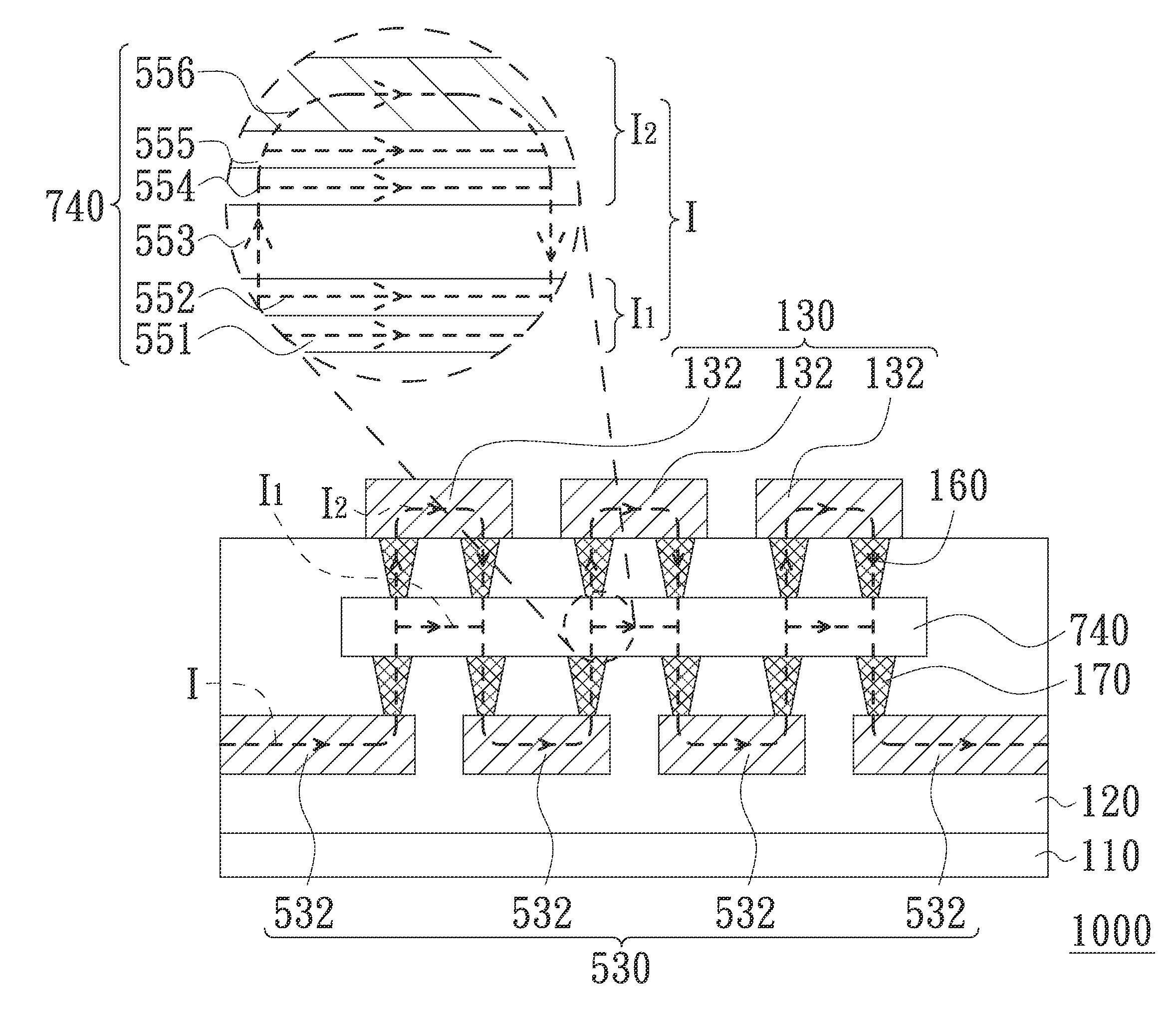
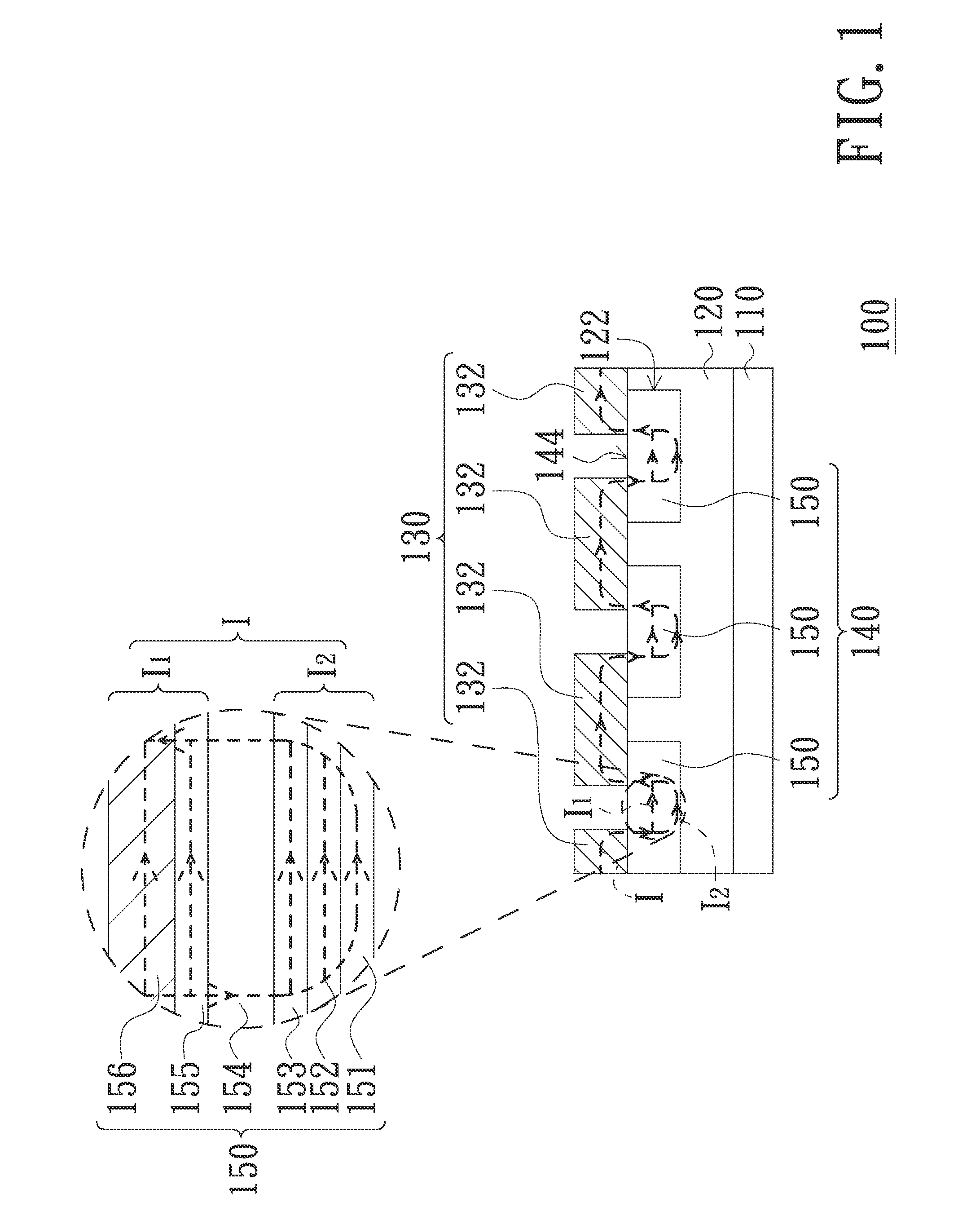
[0022]FIG. 1 illustrates a partial, cross-sectional, schematic view of a TMR sensor in accordance with an embodiment of the present invention. Referring to FIG. 1, a TMR sensor 100 includes a substrate 110, an insulating layer 120, an electrode array 130 and a TMR component 140. The substrate 110 can be, for example, a silicon substrate coved by an insulating material or a silicon wafer having front-end logic circuits. The insulating layer 120 is formed on the substrate 110. The TMR component 140 is embedded in the insulating layer 120. In the present embodiment, the TMR component 140 includes a number of magnetic tunneling junct...


PUM


Abstract

A tunneling magnetoresistance sensor includes a substrate, an insulating layer, a tunneling magnetoresistance component and a first electrode array. The insulating layer is disposed on the substrate. The tunneling magnetoresistance component is in contact with the insulating layer and includes at least one magnetic tunneling junction unit. The first electrode array disposed in direct contact with the insulating layer. The first electrode array includes a number of first electrodes. Each of the at least one magnetic tunneling junction unit is electrically connected to two neighboring first electrodes of the first electrode array to form a current-in-plane tunneling conduction mode.

Description

CROSS-REFERENCE TO RELATED APPLICATIONS[0001]This is a continuation application of an application Ser. No. 13 / 333,951, filed on Dec. 21, 2011, which also claims the benefit of Taiwan Application No. 100123719 of Jul. 5, 2011. The entirety of the above-mentioned patent applications is hereby incorporated by reference herein and made a part of this specification.FIELD OF THE INVENTION[0002]The present invention relates to a tunneling magnetoresistance sensor, and particularly to a current-in-plane tunneling magnetoresistance (CIP-TMR) sensor.BACKGROUND OF THE INVENTION[0003]Recently, the tunneling magnetoresistance (TMR) mechanism has been widely employed for magnetic random access memory (MRAM) and magnetoresistance sensor applications. For example, a tunneling magnetoresistance sensor is frequently used as a rotary position sensor to sense an angular variation with high accuracy. Due to its higher magnetoresistance ratio and higher electrical resistance than a typical giant magnetor...

Claims


Application Information

Patent Timeline
Patent Type & Authority Applications(United States)
IPC IPC(8): H01L43/02H10N50/80
CPCH01L43/02G01R33/098H01F10/3254H10B61/00H10N50/80
Inventor LEE, CHIEN-MINCHEN, KUANG-CHINGLIOU, FU-TAI
Owner VOLTAFIELD TECH
Features
  • R&D
  • Intellectual Property
  • Life Sciences
  • Materials
  • Tech Scout
  • Unparalleled Data Quality
  • Higher Quality Content
  • 60% Fewer Hallucinations
Learn More