Method for reducing flue gas carbon dioxide emissions

Inactive Publication Date: 2014-04-24
FLUOR TECH CORP
View PDF23 Cites 5 Cited by
  • Summary
  • Abstract
  • Description
  • Claims
  • Application Information

AI Technical Summary

Benefits of technology

[0006]The inventive subject matter provides apparatus, systems, and methods in which one may economically and effectively reduce CO2 emissions from flue ga

Problems solved by technology

A significant barrier to removal of CO2 from flue gases is the expense associated with the removal process.
These costs can be very substantial, both in terms of equipment and operations costs and in reduction of plant efficiency.
It is estimated that CO2 capture from emissions generated by a coal-fired power plant increase overnight power generation costs by abou

Method used


Image

  • Method for reducing flue gas carbon dioxide emissions
  • Method for reducing flue gas carbon dioxide emissions
  • Method for reducing flue gas carbon dioxide emissions

Examples


Embodiment Construction

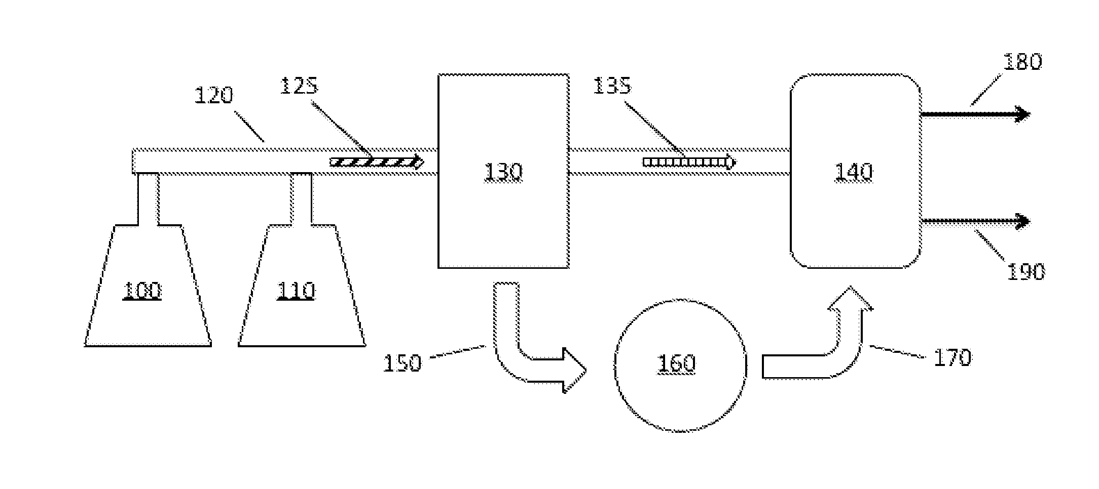
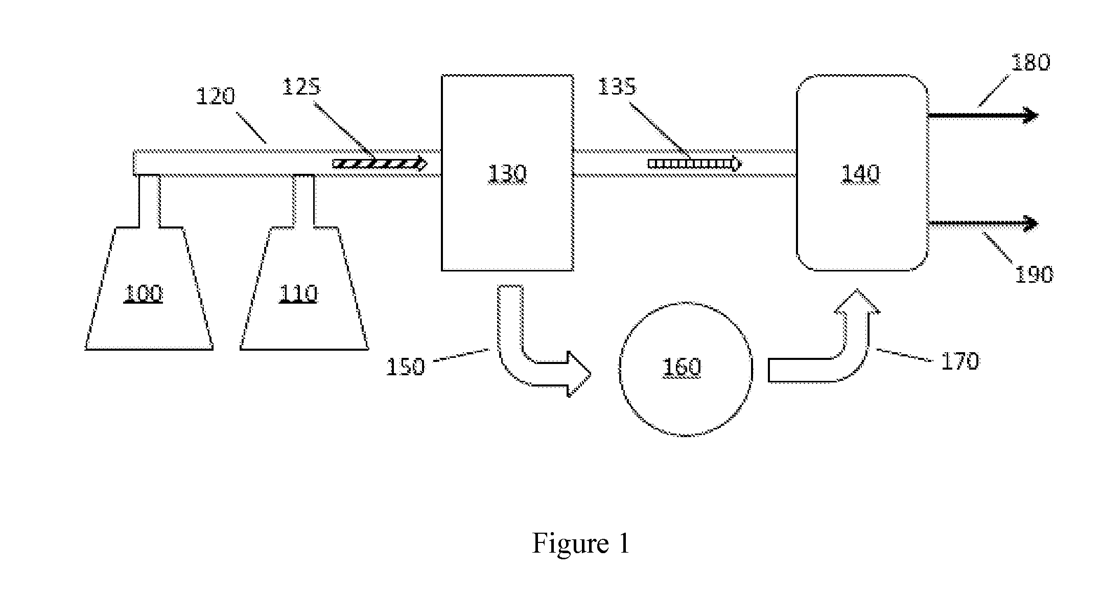
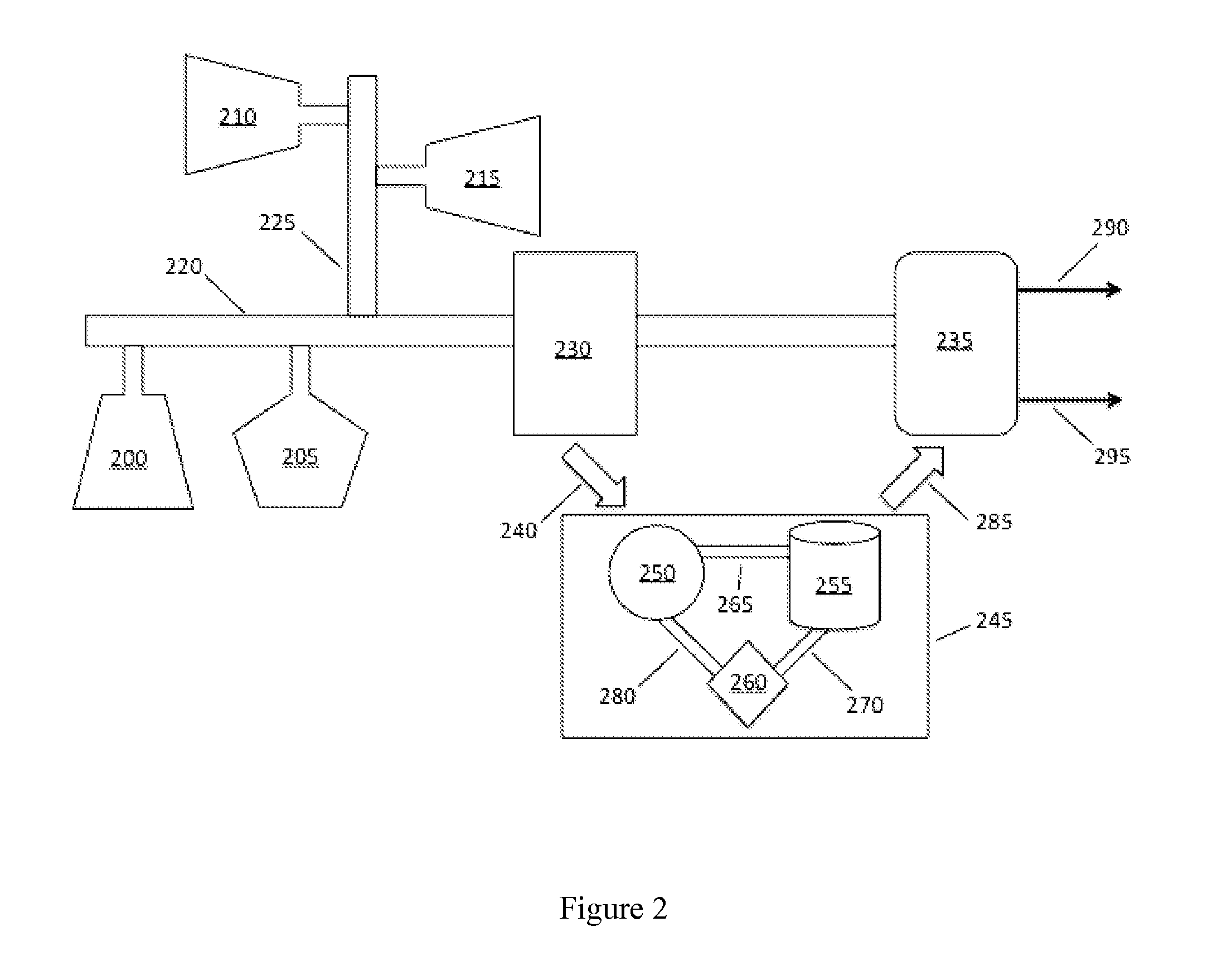
[0012]It should be noted that while the following description is drawn to methods and devices for efficiently recovering CO2 from flue gas, various alternative configurations are also deemed suitable and may be employed to treat any suitable source of CO2 containing gas streams, such as streams from combustion processes in the oil and gas industry, cement plants, lime kiln exhausts, engine exhausts, fermentation processes, hydrogen production plants, ammonia production plants, processing of phosphates, and so on. One should appreciate that compounds other than CO2 may be recovered, including (but not limited to) CO, ammonia, nitrogen oxides, sulfur oxides, volatile organic carbon compounds, and chlorofluorocarbons, from gas streams containing such compounds.

[0013]One should appreciate that the disclosed techniques provide many advantageous technical effects including providing energy efficient recovery of CO2 from flue gas, permitting CO2 to be sequestered and thereby preventing it ...


PUM


Abstract

Plants, devices, and methods are presented which economically and effectively reduce carbon dioxide (CO2) emissions from flue gases by converting heat derived from one or more sources of flue gas to drive a heat engine, which generates power, energy, and/or work that is utilized by a CO2 capture unit coupled to the stream of flue gas. CO2 captured from the flue gas stream may be sequestered and/or utilized for commercial purposes.

Description

FIELD OF THE INVENTION[0001]The field of the invention is capture of CO2 from plant emissions or waste gases. In particular this invention relates to the capture of CO2 from flue gases, especially those produced in chemical or petrochemical plants, power plants, and refineries.BACKGROUND[0002]Flue gases are waste gases typically produced as exhaust from turbines, furnaces, boilers, ovens, steam generators, and similar installations, and are often produced in large quantities by power plants and chemical, petrochemical, and refinery installations. As a combustion product, the composition of flue gas is dependent on the fuel source, however, it will usually comprise nitrogen and unconsumed oxygen from the combustion air, carbon dioxide (CO2), carbon monoxide (CO), trace components like argon, and water vapor. It may further contain volatile organic carbon compounds, nitrogen oxides, and sulfur oxides. Release of many of these compounds (CO2 in particular) to the atmosphere has become ...

Claims


Application Information

Patent Timeline
IPC IPC(8): F01K27/00
CPCF01K13/00F22B37/008F23J15/06F23J2215/50Y02E20/30Y02E20/32
Inventor BALKENENDE, SANDER
Owner FLUOR TECH CORP
Why Eureka
Try Eureka