Gas/liquid contacting vessel and the use thereof in a flue gas treatment system

Inactive Publication Date: 2014-05-01
GENERAL ELECTRIC TECH GMBH
View PDF18 Cites 6 Cited by
  • Summary
  • Abstract
  • Description
  • Claims
  • Application Information

AI Technical Summary

Benefits of technology

[0021]According to some embodiments, the gas/liquid contacting vessel has two gas/liquid contacting compartments. For practical reasons, two gas/liquid contacting compartments are often sufficient for achieving a substantially improved efficiency of the vessel during large variations in the mass flow rate of the flue gas. Two gas/liquid contacting compartments also involve a minimum of adaption of present vessel designs for implementation. An additional advantage is the potential use

Problems solved by technology

Many industrial combustion processes, however, operate at varying loads, resulting in varying flue gas flow rates.
When implementing a CO2 absorption system in a CCPP, the varying flue gas flow rate is problematic because the absorber and regenerator columns in the absorption system are rarely operated near their design point, thereby resulting in both

Method used


Image

  • Gas/liquid contacting vessel and the use thereof in a flue gas treatment system
  • Gas/liquid contacting vessel and the use thereof in a flue gas treatment system
  • Gas/liquid contacting vessel and the use thereof in a flue gas treatment system

Examples


Embodiment Construction

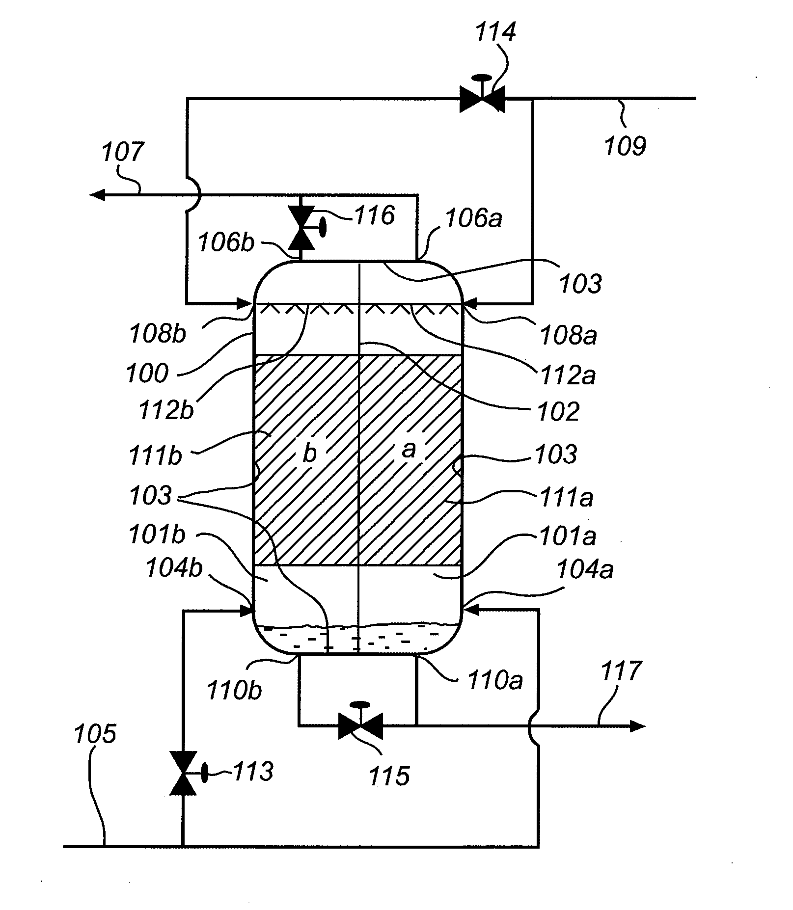
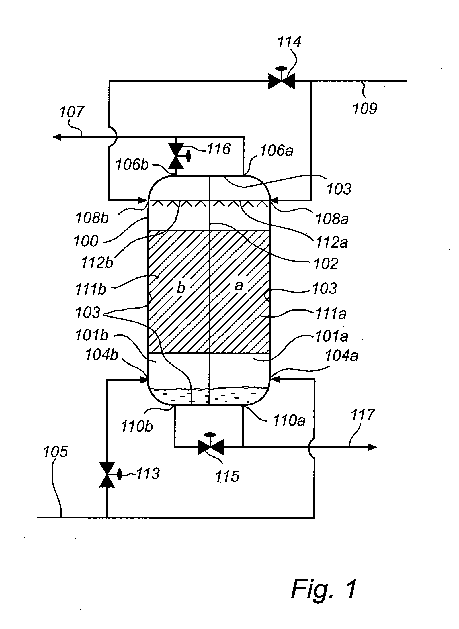
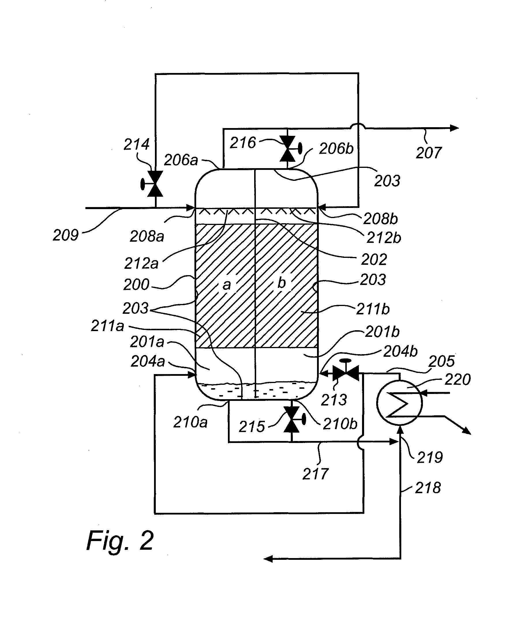
[0046]Herein, the inventive concept as applied to the absorber and / or regenerator vessels of an amine absorption based CO2 capture system will be described in detail with reference to the drawings. It is realized that the inventive concept may also be applied to other gas / liquid contacting components of a flue gas treatment system, for example water wash units for removal of trace contaminants, strippers and direct contact coolers / heaters.

[0047]The term “gas”, as used herein, is intended to encompass gases as well as liquids in vapor form. Specifically, the gas processed in the gas / liquid contacting vessels described herein may be a gas, such as CO2, or a liquid, for example water, in vapor form.

[0048]The term “in fluid contact with” with regard to two components of a

[0049]system, one component being upstream of the other, then during the normal operation of the system, essentially all of the fluid passing through

[0050]the system passes first through the upstream component and then ...


PUM

PropertyMeasurementUnit
Volumeaaaaaaaaaa
Mass flow rateaaaaaaaaaa

Abstract

The proposed invention relates to a gas/liquid contacting vessel (100) for treatment of a gas stream at varying mass flow rates, said vessel comprising at least two distinct gas/liquid contacting compartments (101a, 101b) separated from each other by a substantially vertical partition (102), each compartment having a gas inlet (104a, 104b) and a liquid outlet (110a, 110b) near a bottom end thereof and a gas outlet (106a, 106b) and a liquid inlet (108a, 108b) near a top end thereof, and a mass transfer device (111a, 111b) arranged between said bottom end and top end, wherein one of said compartments is operable for gas/liquid contacting independently of another of said compartments. The proposed invention further relates to a flue gas treatment system for removal of carbon dioxide (CO2) from a flue gas using a liquid absorbent and to a power plant comprising such a gas/liquid contacting vessel or flue gas treatment system.

Description

FIELD OF THE INVENTION[0001]The proposed invention relates to a gas / liquid contacting vessel for treatment of a gas stream, and to a flue gas treatment system for removal of carbon dioxide (CO2) from a flue gas using a liquid absorbent.BACKGROUND[0002]In the combustion of a fuel, such as coal, oil, peat, waste, etc., in a combustion plant, such as those associated with boiler systems for providing steam to a power plant, a hot process gas (or flue gas) is generated. Such a flue gas will often contain, among other things, carbon dioxide (CO2). The negative environmental effects of releasing carbon dioxide to the atmosphere have been widely recognized, and have resulted in the development of processes adapted for removing carbon dioxide from the flue gas generated in the combustion of the above mentioned fuels.[0003]Many of the developed flue gas cleaning processes involve contacting the flue gas with an absorbent liquid capable of absorbing CO2 from the gas to produce a flue gas whic...

Claims


Application Information

Patent Timeline
IPC IPC(8): B01D53/14B01D53/18
CPCB01D53/1475B01D53/1425B01D53/18B01D2257/504B01D2252/102B01D2252/204B01D2258/0283Y02E20/16Y02C20/40Y02A50/20
Inventor CARRONI, RICHARDAGOSTINELLI, GIAN-LUIGIKOSS, ULRICH
Owner GENERAL ELECTRIC TECH GMBH
Why Eureka
Try Eureka