Bearing device for turbocharger

a bearing device and turbocharger technology, applied in the direction of machines/engines, stators, liquid fuel engines, etc., can solve the problems of difficult to stabilize the fully floating bearing, and achieve the effects of improving the stability of rotation oscillation, noise reduction, and reducing the number of parts

Active Publication Date: 2014-05-01
MITSUBISHI HEAVY IND LTD
View PDF8 Cites 27 Cited by
  • Summary
  • Abstract
  • Description
  • Claims
  • Application Information

AI Technical Summary

Benefits of technology

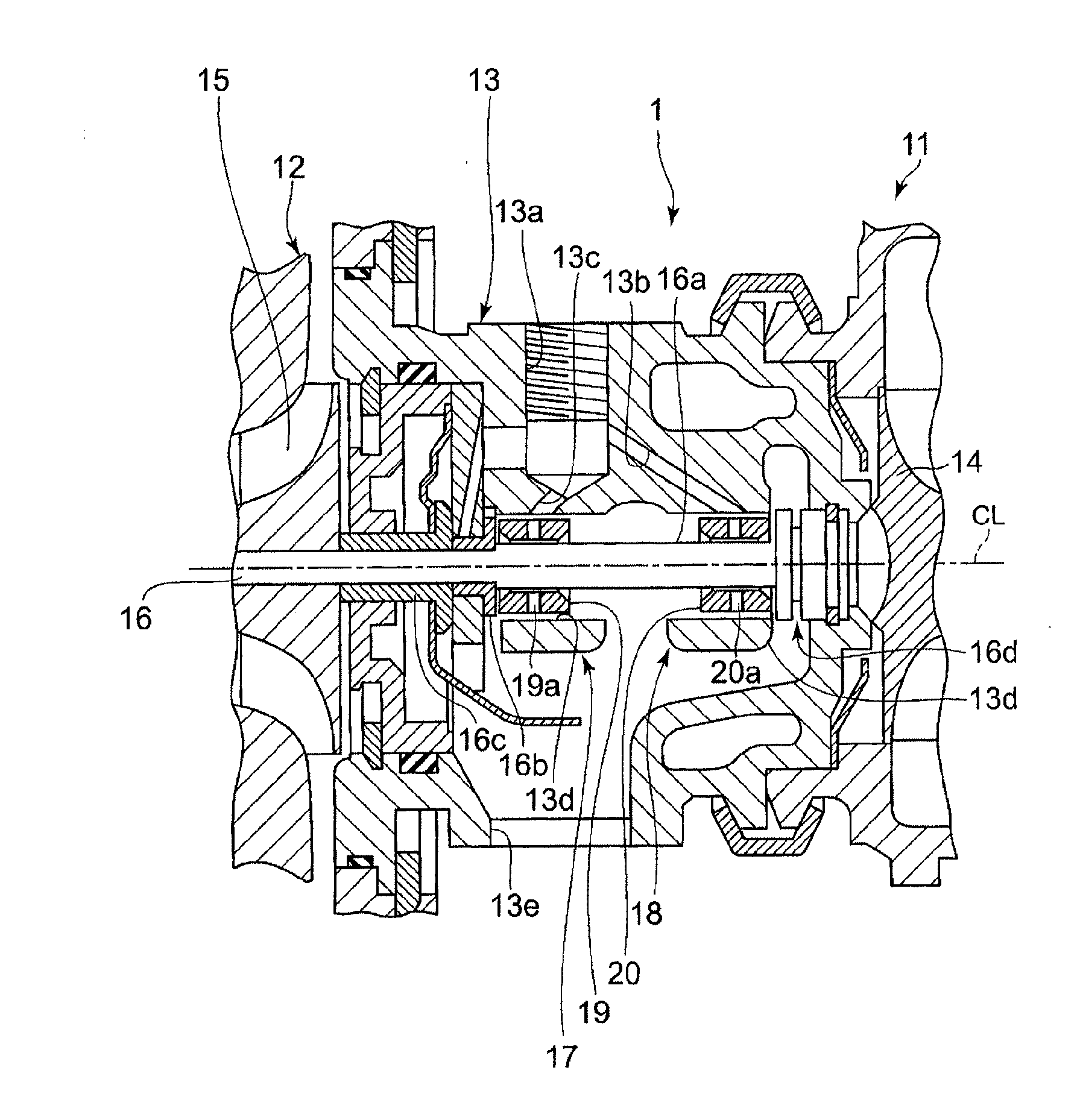
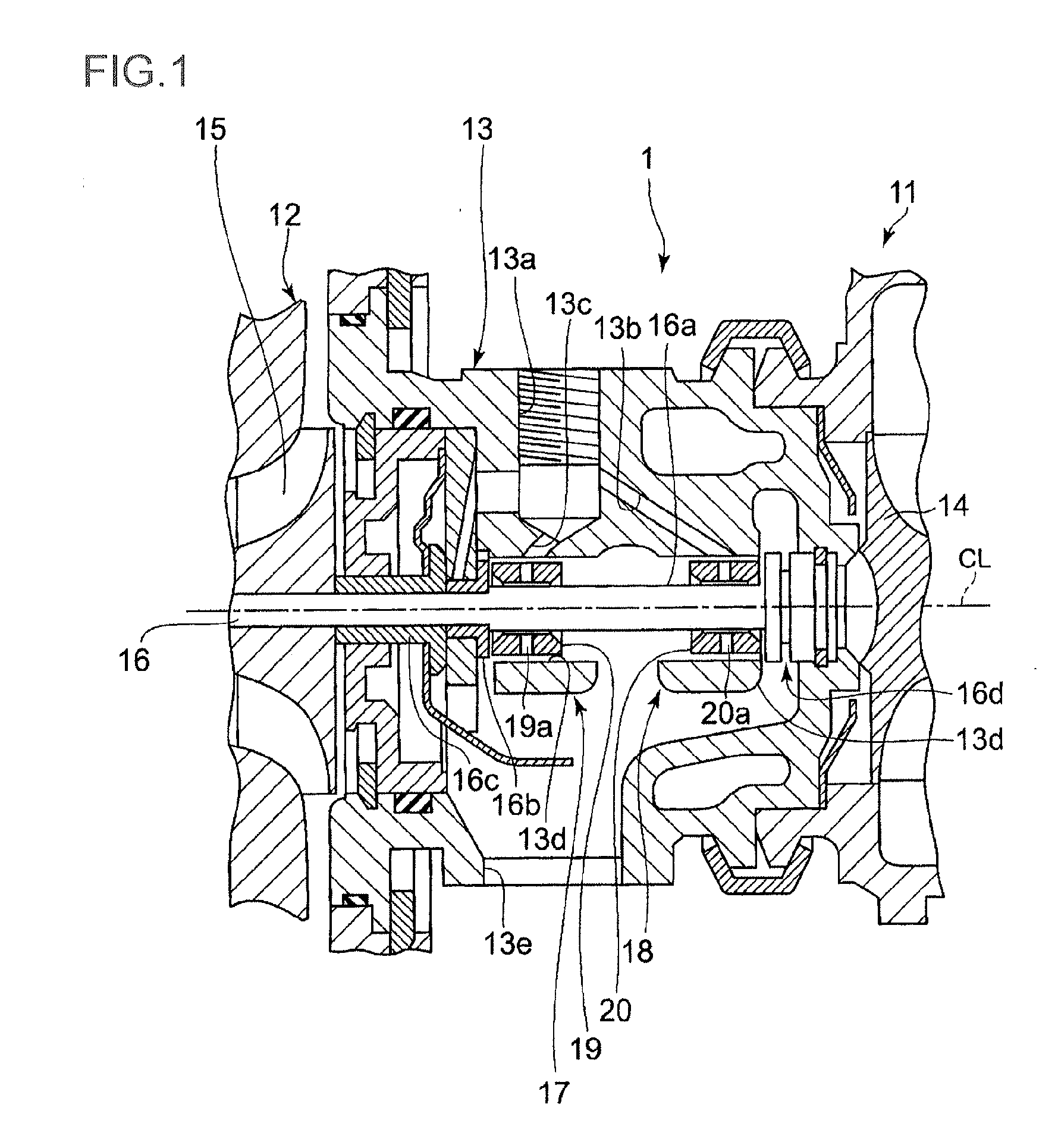
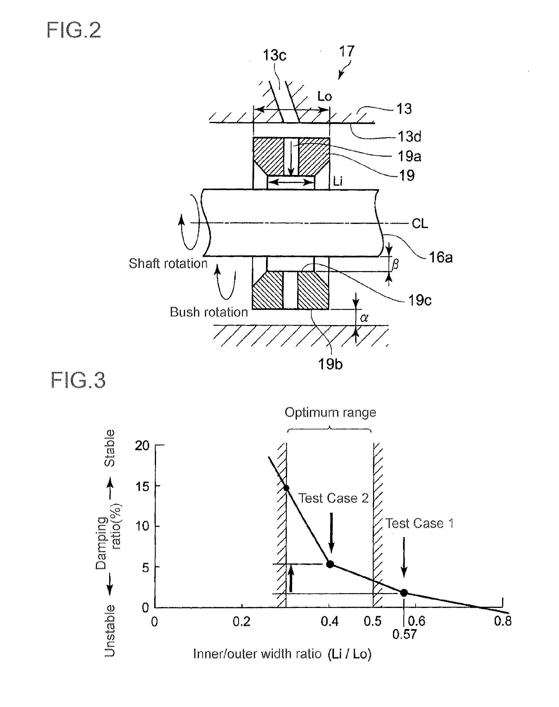
[0035]According to the present invention, by configuring each of the first and second bushes so that the inner bearing width is smaller than the outer bearing width, it is possible to maintain the co-rotation amount of each floating bush at an appropriate rotation speed with respect to the rotation speed of the rotor shaft during high-speed rotation of the rotor shaft, and improve the rotation oscillation stability so as to achieve the noise reduction effect.
[0036]Further, by forming the outer bearing width larger than the inner bearing width, it is possible to maintain the damping effect on the floating bush bearing and the housing.
[0037]Furthermore, as the first and second floating bushes have the same configuration, it is possible to reduce the number of parts, and facilitate processing and assemblability. As a result, the risk of misassembling can be lowered and stable processing quality and cost reduction can be achieved.

Problems solved by technology

This change makes it difficult for the fully floating bearing to be in a stable state, thereby suppressing self-excited oscillation.

Method used


Image

  • Bearing device for turbocharger
  • Bearing device for turbocharger
  • Bearing device for turbocharger

Examples


first embodiment

[0084]FIG. 4A illustrates a low friction treatment provided on an outer peripheral part of the floating bush according to a FIG. 4A shows an enlarged cross-sectional view of the floating bush 19 provided with the low friction treatment on the outer peripheral part to cause co-rotation of the floating bush 19 at an early stage in the low-speed rotational range of the rotor shaft 16.

[0085]On the outer peripheral surface of the floating bush 19, DLC (Diamond Like Carbon) coating 19d is provided as the low friction treatment.

[0086]The DLC used here may be metal-containing DLC (WC: tungsten carbide, Si: silicon), hydrogen containing DLC, or the like.

[0087]The DLC coating is normally formed by, but not particularly limited to, chemical vapor deposition (CVD)

[0088]The DLC film is hard and fragile and thus, to improve adhesion of the film to a base material (the floating bush), a substrate material may be provided between the base material (the floating bush) and the DLC film. The substrat...

third embodiment

[0095]FIG. 4C illustrates a low friction treatment of a third embodiment in (C1). FIG. 4C shows in (C2) a longitudinal cross-sectional view of (C1) in the radial direction. In a floating bush 30, a center groove 30d is provided in an outer peripheral surface 30a of the floating bush 30 over the entire circumference of outer peripheral surface 30a approximately at the center of the outer peripheral surface 30a in the bearing width direction. The center groove 30d communicates with an oil supply hole 30c which penetrates the floating bush 30 from the outer peripheral surface 30a to the inner peripheral surface 30b.

[0096]As illustrated in (C2) of FIG. 4C, the lubricating oil fed from the lubricating oil path 13c flows to a lower part of the floating bush 30 via the center groove 30d, thereby filling the space between the floating bush 30 and the bearing portion 13d. As a result, the friction resistance at the start of rotation of the floating bush 30 can be reduced.

fourth embodiment

[0097]FIG. 4D illustrates a low friction treatment of a fourth embodiment in (D1). FIG. 4D shows in (D2) a longitudinal cross-sectional view of (D1) in the radial direction. In a floating bush 35, an oil supply hole 35c is provided approximately at the center of the outer peripheral surface 35a of the floating bush 35 in the bearing width direction. The oil supply hole 35c penetrates the floating bush 35 from the outer peripheral surface 30a to the inner peripheral surface 30b.

[0098]On both sides of the oil supply hole 35c of the outer peripheral surface 35c in the bearing width direction, a pair of edge grooves 35d, 35d is formed over the entire circumference of the outer peripheral surface 35a. In each these edge grooves 35d, 35d, a transverse groove 35e is provided for each oil supply hole 35c so that the edge groove 35d communicates with the oil supply hole 35c.

[0099]As illustrated in (D2) of FIG. 4D, the lubricating oil fed from the lubricating oil path 13c flows to a lower p...


PUM


Abstract

It is intended, with respect to a first floating bush bearing disposed on a compressor housing side and a second floating bush bearing disposed on a turbine housing side, to improve oscillation stability when a turbine rotor revolves at a high speed, reduce the number of parts, and facilitate processing and assemblability. Provided are a bearing housing (13) for a turbocharger (1), a rotor shaft (16) passing through the bearing housing (13), a first floating bush bearing (17) interposed between the bearing housing (13) and the rotor shaft (16) and disposed on a compressor housing (12) side and comprising a first floating bush, and a second floating bush bearing (18) that has the same shape as the first floating bush bearing (17) and is disposed on a turbine housing (11) side and comprises a second floating bush (20). The inner bearing width (Li) of the first and second floating bushes is formed to be smaller than the outer bearing width (Lo) by the same proportion in both bushes.

Description

TECHNICAL FIELD [0001]The present invention relates a floating bush bearing which is suitable for a rotary machine having a high-speed rotation shaft, such as a turbocharger.BACKGROUND ART[0002]A floating bush bearing includes a floating bush rotatably provided in a space between a rotation shaft and a bearing housing. The floating bush bearing is configured so as to supply pressurized lubricating oil from the bearing housing to a space between an inner peripheral surface of the bearing housing and an outer peripheral surface of the floating bush and also to a space between an inner peripheral surface of the floating bush and the rotation shaft via an oil supply path provided in the floating bush in the radial direction.[0003]The floating bush bearing is configured to support the rotation shaft stably while suppressing its oscillation by a damping effect of the oil film of the lubricating oil formed in these spaces and also to prevent seizure.[0004]FIG. 7 is a detailed view of a flo...

Claims


Application Information

Patent Timeline
Patent Type & Authority Applications(United States)
IPC IPC(8): F01D25/16
CPCF01D25/16F02M55/00F01D25/166F01D25/22F02B39/14F16C17/18F05D2220/40F05D2250/61F16C2206/04F16C2202/54F16C17/02F16C27/02F16C33/043F16C33/1065F16C2240/40F16C2360/24F16C17/26F01D25/18F05D2240/54
Inventor NISHIDA, HIDEAKI
Owner MITSUBISHI HEAVY IND LTD
Why Eureka
Try Eureka